The Junker is one of the finest telegraph keys ever manufactured.
In 1926, engineer and marine captain Joseph Junker, founded a factory in Berlin which made equipment for radios and submarines. He was the creator of the Junker telegraph key.
At the end of World War II, the factory was moved to Honnef just before Joseph died in 1946.
German precision - Micrometer gap adjustment
The phrase "German precision" is applicable here. Historically, German engineers seem to go above and beyond what is minimally required for a design and often "over-engineer" their products. This key is a perfect example. The Junker excels in the precision of its construction, and may have the most controllable gap adjustment of any straight key in the world, resulting in the ability to send very clean CW.
Ball-bearing plunger under the gap adjustment
The knob at the rear of the key moves in precise clicks controlled by a ball bearing plunger under the knob, engaging small detents underneath the wheel. Each click moves the gap one-tenth of a millimeter. That is "very" precise.
click stop gap adjustment
Unlike most straight keys when the gap is set at it's minimum it's calibrated to actually be a minimum gap and not allow the contacts to touch. I don't have a feeler gauge thin enough to measure the gap but it's there. It's so small, that I can't discern the lever actually moving when I operate the key, but it makes clean contact with zero mushiness and nearly effortless operation of the key.
gap at 2-clicks
The lever force, or tension adjustment is singular as well. The smaller knob on the left trunnion base moves a cantilever under the base of the key that moves a plate under the lever spring. So rather than compressing the spring from the top of the lever at it's narrowest, it is compressed smoothly from the base up into the lever. Just amazing!
Some Junkers came with an RF suppression coil comprised of a many turns of hand-wound, insulated wire tied into a tight loop and held with ties fitted up into a circular recess in the base of the key. My key did not have the RF suppression coil, which is fine, since I am not operating a high-voltage keying circuit that might benefit from the coil. I've read that some users have encountered problems due to the fine wire of the RF coil providing too much resistance and have bypassed it. No need here.
under the base of the key, notice the armature for adjusting the lever tension.
In use
Most straight keys I've used in the past two years employ a Navy-knob style grip that I've grown accustomed to. The Junker has a lower (about 2.5" above table), flat lever disc. It's odd how used to the Navy style grip I've become. I practiced for about 15 minutes trying various grips. I still operate with my arm in free-space and I imagine with this key I'm supposed to rest my elbow on the desk but I don't have room for that at my station so I operate with the key at the edge of the desk.
Anyway, I settled for now on sort of a loose fist style grip where I'm resting the first knuckle of my middle finger on the dish of the key while lightly gripping the disc. Seems to work and the more I operate the more comfortable I'm becoming with it.
The level of adjustment is truly amazing. Being able to quickly change gap adjustment during a QSO to relieve fatigue or just try a different spacing, without messing around with a set nut, or worrying about actually closing the contact was novel, and fun.
A bit of refinishing
Not being terribly enamored with the rough appearance of the old key I removed the aluminum corrosion from the cover and the heavy handed brushed paint from the base with a bit of light sanding, and sprayed it with hammered silver. I also made a proper cable and plug for it. Now it's fresh as a German daisy.
A re-spray has spruced it up
Video
The demonstration QSO below was my first contact using the Junker after a few minutes of practice. I'm sending at about 17-18wpm. After a couple more QSOs and bit more practice I was easily sending at 20wpm which is faster than I'm comfortably able to operate my other straight keys.
Following the introduction to the Junker is a full length QSO using the Junker on it's first Amateur radio QSO with W4PCA.
Compared to my other favorite key, Navy Flameproof
I'm looking forward to using this Junker and comparing it head-to-head with my Navy Flameproof. Initial impressions between the Flameproof and the Junker give the nod to the Junker. The Flameproof was previously the most controllable and precise straight key I owned but the Junker makes it feel mushy in comparison. I do prefer the grip of the Navy, so time will tell whether I become as comfortable using the Junker as I am the Navy Flameproof.
That's all for now
So lower your power and raise your expectations...
Due to the inherent rhythm in Morse Code, some stuff is just fun to hear. If you swing your Bug a bit or don't have the most perfect 3:1 DAH-DIT element timing it can sound even more interesting.
The old timers all know this stuff but for those of us new(ish) to CW there are still these little gems we keep finding... like how sending the words BENS BEST BENT WIRE sound in CW when they are all crammed together .
If you've never played around with rhythmic sounding words during your off-air practice just give it a whirl. If you do it on a bug with a bit of liberal timing it can be even more fun.
QRP operators strive to make the most out of a little. So when we receive a signal report it means a lot to us. But the common signal report, given using the R-S-T System, seems often to be misunderstood by some amateur radio operators.
RST has 3 elements:
R stands for Readability. How easy or difficult is it to copy the characters or words being sent on a scale from 1 to 5, with 1 meaning unreadable ranging up to 5 meaning perfectly copy-able.
S stands for Signal Strength. How strong is the signal on a scale from 1 to 9, with 1 being barely perceptible up to 9, being extremely strong.
T stands for Tone. This is only used to describe a CW signal's tone. Given modern transceivers there are few cases where you'd send anything other than a 9 meaning perfect tone, devoid of ripple or modulation. You'll rarely hear a report with a Tone report other than 9, but if you hear ripple or modulation artifacts you may send lower numbers but it will likely just confuse the other operator. If you hear chirp (a rising or falling tone) you may wish to append a 'C' to the RST to indicate that.
I want to concentrate on Readability and Signal strength.
Readability
I believe most of us are guilty of focusing on the signal strength portion of the report rather than readability. But readability can convey a lot to the operator receiving the report.
For instance if you have a lot of local noise or if the band is noisy due to magnetic disturbance or there's QRM or QRN readability may be difficult. Similarly, if the operator is using poor technique and running letters or words together that affects readability.
It's possible that signal strength may be good or even moderately strong (6 or 7) but for some reason copy is difficult. It would be worthwhile to send a 2 (Barely readable, occasional words distinguishable) or a 3 (Readable with considerable difficulty) for the 'R' portion of the signal report as in 359. Then follow up with WITH QRM or WITH POOR SPACING, to make the other operator aware that you're having trouble copying.
I will occasionally have an operator send me a 3 for R but it seems to always be related to low signal strength. If someone sends you a 3 or a 4 and it's not followed by an equally low signal strength number inquire as to the difficulty in readability. It may be something you can correct on your end.
Signal
Signal seems obvious but it's not.
I believe that many operators use the reading on their S-meter to report the Signal strength but different manufacturers calibrate their S-meters quite differently. The difference between S-units is supposed to be 6 dB but that's often not the case. On many rigs the use of the preamp or the attenuator also effects the displayed S-meter reading. So the S-meter is not an accurate reflection of what Signal strength is supposed to convey.
My old Ten-Tec Century/21 doesn't even have an S-meter. Neither do my homebuilt QRP radios.
So, what should we be using? Well how about the actual meaning of the system:
Faint—signals barely perceptible
Very weak signals
Weak signals
Fair signals
Fairly good signals
Good signals
Moderately strong signals
Strong signals
Extremely strong signals
Obviously this is a subjective report, but on my KX3 my S-meter may read 2 when the signal actually sounds Good (6), so I send a 6 even though the meter reads 2. If I were to send the other station the S-meter reading of 2 they'd assume I'm barely copying them, because I sent them a 529.
I think you can start to see the point. Use the system as it was designed, before radios had S-meters and the Signal report will have more meaning to the station receiving the report.
My Ten-Tec C21 doesn't have an S-meter but it does have AF and RF gain controls. I will commonly run my AF gain at a high level and use the RF gain to control the volume of the received signal. This increases the SNR (signal to noise) and gives me a relative gauge of how strong the sender is. If I have my RF gain turned all the way down and still clearly hear the other station they have an extremely strong signal (9). If I have to turn my RF gain all the way up just to copy then the signal is very weak, or faint (2 or 1). In between those extremes I offer a relative report based on the signal strength I am hearing.
So, use the system as it was intended
So, reconsider how you give a signal report. Think about the original intent of the R-S-T System and you'll be conveying far more information in your report that may help the other station know for certain how they are being heard.
I start most QSOs at QRP levels. If the other station sends me a report that is below a 5 in readability or a signal strength 5 or below I change antennas or raise power, if I'm able, to make their copy of my station more pleasurable, but if they send me a 599 when they are barely copying me or losing me in QSB then how can I know to make a change?
Maybe this is a radical idea but for my own operation I will strive to start sending more accurate reports and help the other station truly know how they are being copied.
Learning the characters of Morse Code is just the start. Letters make up the words, but words make up the language.
I practice copying random words in morse code regularly. Along with actually getting on the air and having QSOs it's a crucial to learn common words in order to be comfortable copying ragchews, outside of standard exchanges.
Videos
The following videos contain the top 100 English words along with the text of the words at different speeds up to 38 wpm. At the higher speeds you will find that the characters disappear and you begin to only hear words.
I hope you find this instructive.
15 WPM
20 WPM
25 WPM
38 WPM -- Rock On!
That's all for now...
So lower your power and raise your expectations
72/73
Richard AA4OO
In the past couple of years my copy speed has increased to the point where I'm able to have QSO’S at 25 wpm, but I still remember when 5 wpm was a struggle.
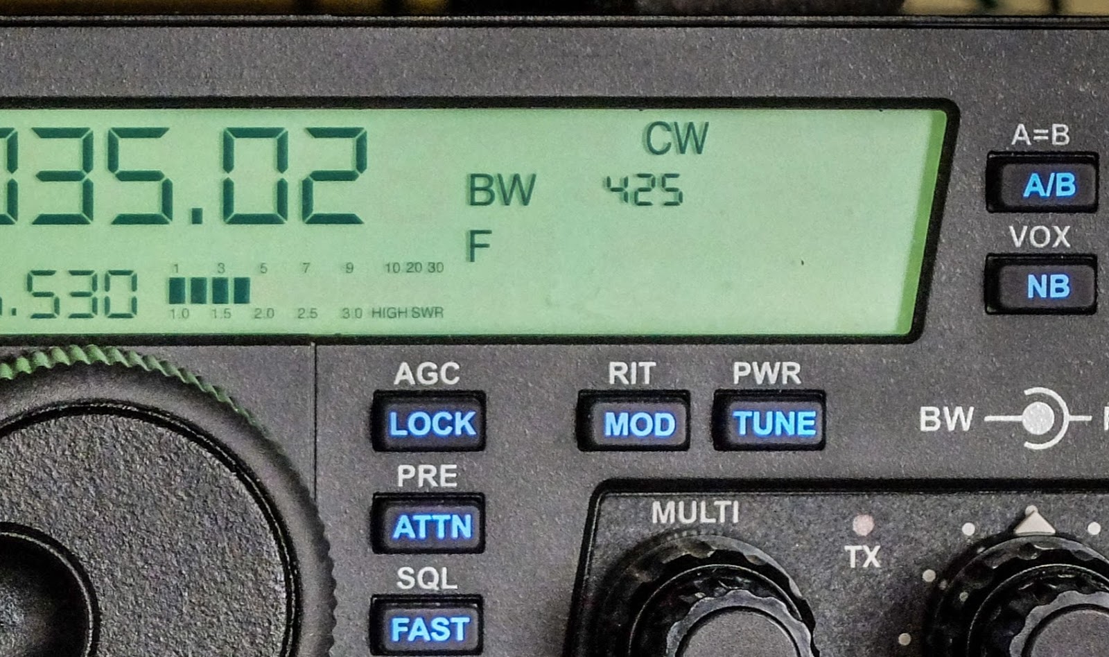
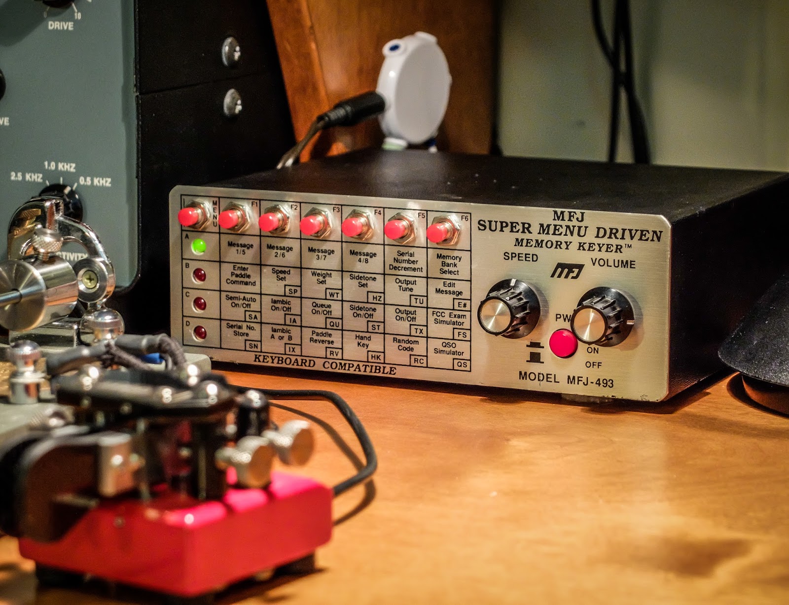
My keyer dates back to when morse code proficiency exams were still a thing to study for and my MFJ-493 keyer has a FCC Exam Simulator mode. I set the speed to 17 wpm with a Farnsworth spacing of 5 wpm and let it rip.
This was painfully slow to listen to, but a little over 2 years ago when I rebooted my Morse Code learning for using QRP I would have struggled to copy it. So I'm posting a video with the simulated exam and for those of you new to studying morse code or just feel stuck, you may wish to use this for practice.
I've included the real time text sent in the video so you can check yourself or see what you've missed.
If you're still working to copy 5wpm be encouraged that with practice your speed will improve.
Simulated Novice Proficiency Test
That's all for now... So lower your power and raise your expectations
72/73
Richard, AA4OO
Sometimes I needlessly struggle with a problem because I'm cheap.
My Vibroplex Vibrokeyer was manufactured in 1960. My Vibroplex Bug was manufactured in the mid 1970s. In both cases the once flexible, non-skid rubber feet have since turned to hardened rubber fossils. In order to use the keys without them skating all over the desk I employ a variety of non-skid solutions, except for the obvious.
For some reason I seem to have to move stuff on my desk all the time. I guess I'm never content and constantly reorganize the station and accessories. Inevitably I misplace a rubber mat or some rubberized shelf liner sticks out from under a key in an unsightly manner. In general it makes the station look shoddy.
2B Radio Parts, provide replacement parts for Bugs, paddles for various makes of keys. I ordered Replacement Vibroplex Bumpers (6 Bumper Pack). I wasn't aware the 'feet' were called 'bumpers', but there you have it... I have new rubber baby buggy bumpers for my bug and vibrokeyer.
The 6 bumper pack replaced the feet on both keys. In case you never noticed, many keys, including those made by Vibroplex, have 3 feet rather than 4. It keeps the key from rocking on a surface that isn't entirely level or flat.
Parts is Parts
The replacement feet... err... bumpers from 2B, fit fine. They were nearly an exact match for the old feet on the 1970s bug but were a smidge taller and slightly different design than those on the 1960 Vibrokeyer. The older key had a chambered, internal design that I'd guess had a bit more cushion back when it was new. 57 years later, the rubber foot is a brittle relic of its former self.
new bumper left, 1960 Vibrokeyer bumper right
new bumper left, 1960 Vibrokeyer bumper right
Ahhh, no more slip siding away
The old feet are simply held on by countersunk machine screws and the receiving holes in the new bumpers fit without a hitch.
Shod with new boots, shoes, feet, bumpers, whatever
My Vibroplex Bug has a more solid disposition as well now
The moral of the story is stop being cheap and buy some new feet!
That's all for now... So lower your power and raise your expectations P.S. Oh, speaking of which (lowering your power and raising expectations)... I was sending out my call on 7030 unsuccessfully a couple nights ago, for about 10 minutes. I was using my TenTec Century/21 at 5 watts QRP and getting lousy spots on RBN (6 to 9dB SNR). I decided to keep sending CQ a couple more minutes and was finally answered by S51MF, Franz in Slovenia, 4700 miles away. You just never know what your QRP signal is going to net you. 72/73 Richard, AA4OO http://hamradioqrp.com
Iambic mode keying occurs when you squeeze dual lever paddles, and then release both paddles simultaneously. If the keyer is in mode A, it will finish sending the current element (dit or dah), and then stop. If the keyer is in mode B, it will finish sending the current element, then send another element, and stop.
Electronic keyers provide Iambic modes to allow for fewer strokes while keying, thus improving keying efficiency
Mode B requires fewer strokes than Mode A
You can stop reading now, if you'd like. The remainder is just me prattling on.
Iambic?
Iambic modes were a mystery when I began learning the code. My first transceiver defaulted to Mode A and I had Bencher paddles so I got used to squeeze keying a bit but only in Mode A. When I got my TenTec Eagle, its internal keyer only supported Mode B and that totally screwed me up. I didn't know what was going on and thought something was wrong with the radio. I ended up using my old HamKeyer external keyer with the TenTec Eagle rather than figure out Iambic mode B. But, as with most things in this hobby, I eventually decided I wanted to understand what the Iambic modes were about and how to use them.
Iambic refers to a pattern of syllables, typically in a line of poetry. There are various "meters" that describe different syllabic patterns. Iambic is a pattern that has a short sound followed by a long sound, as in deDUM or ditDAH. If you've ever used a CW dual paddle key with an electronic keyer and squeeze the paddles you'll be greeted with ditDAH ditDAH ditDAH ditDAH ditDAH ... Aha! Iambic meter.
Iambic keying saves strokes. Comparing the number of strokes necessary to key all letters of the alphabet and all digits with different keys and keyers yields the following result, provided the operator is consistently squeezing with twin-lever keyers:
Unless you like to practice sending Walt Whitman poems, there's not much direct relationship between ham radio and poetry. But I've read CW operators referring to Iambic "paddles" or advertising an "Iambic paddle".... Well, I'll argue there's no such thing as an Iambic paddle because a paddle by itself whether it is a single lever paddle or dual lever cannot make an Iambic pattern on it's own. A paddle is only half a CW key, it needs a keyer, and the code in the keyer is what makes Iambic possible!
Whew! Alright, I got that off my chest. I'm not sure what get's me so worked up about this sort of "yes it matters" things... I blame being locked in the basement as a child, but that's fodder for another blog post...
Iambic keying requires a dual-lever paddle and an electronic keyer
Ok, back on topic; a dual lever paddlecan be used withan electronic electronic keyer, that supports Iambic mode(s). A single lever paddle when used with an electronic keyer cannot make use of Iambic mode, so called, squeeze keying modes. So when we talk about using a paddle with an electronic keyer for Iambic mode keying we are referring to a dual-lever paddle connected to an electronic keyer (or the electronic keyer circuit built into a transceiver).
A two lever paddle is required because the Iambic modes of the keyer are employed while both levers are pressed and released at the same time. What happens when both levers are released simultaneously depends on the Mode that the keyer is using.
A dual lever paddle
The Modes only matter when the paddles are squeezed and released together
The difference in the two modes only matters when you release both paddles simultaneously. So if you never release both paddles together, you won’t see a a difference.
Mode A -- The keyer will complete the element being sent (either a dit or a dah) when the paddles are released
Mode B -- The keyer sends an additional element when the paddles are released
You can avoid Iambic Modes altogether
You can avoid interaction of either Iambic mode if you release each paddle as it finishes its final element rather than releasing them together. For example with the letter "C", DAHditDAHdit, release the DAH paddle during the final DAH, and release the dit paddle during the final dit. For a letter ending in DAH like "A", ditDAH, release the dit paddle during the final dit, and then release the DAH paddle during the final DAH. This will produce the correct code whether the keyer is in Iambic mode A or B.
Video
The following video shows the different modes in action...
To Squeeze or Not to Squeeze? That is the question
Ok, I'll admit squeeze keying allows you to send kinda lazy, and it's cool when you demonstrate CW to someone how little motion you can use with paddles compared to a straight key. However, there are numerous articles out there for and against squeeze keying, and I think they both make good points but some proponents of each treat it as a somewhat religious doctrine and I just can't get that serious about it.
Personally I enjoy squeeze keying when I'm sending at 20 words per minute or less because it's relaxing and is a bit nerdy to let the keyer do a dit of extra work for me now and again (see what I did there). But I start making more mistakes as the speed increases past 23 wpm and I absolutely can't squeeze-key above 27 wpm. I have trouble using a dual paddle above 25wpm because I accidentally squeeze key when I shouldn't and Iambic stuff occurs accidentally. I could likely improve with practice, but higher speeds are easier for me with my Bug or a single paddle key so I haven't really tried to speed up using dual paddles. For now it's not much of an issue because I rarely QSO above 23wpm. I only key above 25wpm when working a DX station and it's such brief bursts that I just use my bug or send my "5NN TU dit dit" using a keyer macro.
History of Keyers and modes
The following excerpt is used by permission of Karl Fischer, DJ5IL. Karl has written an excellent article entitled "All about Squeeze-Keying" available in its entirety at:www.cq-cq.eu
In 1951 an electronic single-lever key was described1 which used 5 tubes to send self-completing dot- and dash-elements with automatic spacing between letters and words. But its continuously running time-base resulted in an uncontrollable beast so that the author himself wrote he does "not feel that any but the most feverish electronic key enthusiasts will wish to build one of these infernal, maddening machines", but nevertheless he hoped that the idea might provide an inspiration for further development.
John Kaye, W6SRY, accepted that challenge and came up with a rather ingenious design which he published2 as the Ultimatickey in QST magazine in 1953 . The circuit is based on 3 tubes and 7 relays and sticks to the basic idea of a continuously running time-base, which is the only weak spot of his design: pulses from the time-base trigger the generation of dot and dash-elements, and so they do not start immediately with the closure of a key contact but only with the next pulse. By addition of dot/dash-memories he avoids dropping of leading elements and transforms the beast into a beauty: once a contact of the singlelever key has been closed, that closure is retained by a memory-relay contact parallel with the key contact and the associated dot- or dash-element is properly generated as soon as the trigger pulse arrives, even if that key contact is open again or the opposite key contact is closed by then. The dot/dash-memory relays are reset and their contacts opened by the closing contacts of the associated dot/dash-generator relays. The dot/dash-memories are independent of each other and because a dot and dash often are rapidly stored together before keying starts, a sequencing circuit retains the proper order in which the dot/dash-generators are initiated.
This combination of independent dot/dash memories which not only avoid dropping of leading elements but also provide tremendous timing leeway with sequencing allows the storage not only of a single dot or dash but of a whole dot + dash or dash + dot sequence. While this initial design still used a single key lever, his next version3 which appeared in 1955 was the first twin-lever electronic keyer and ancestor of the modern squeeze-keyers which we use today, and it is this key’s action that gave the "ultimatic" mode its name. The circuit is based on 11 tubes and only one relay and the time-base, memory and sequencer are functionally identical to the first version. But because contrary to a single-lever both contacts of a twin-lever key can be closed at the same time, a seizure circuitry was added: whenever a lever makes contact, it seizes control and the subsequent elements correspond to that lever until the other lever makes contact or the lever is released.
While one lever contact is closed the twinlever Ultimatic generates a string of dot- or dash elements,
exactly like any single-lever keyer does. However, when the levers are squeezed so that both contacts are closed, it generates a string of elements from whichever lever was pressed last. So any closure of a lever contact guarantees at least one element of that type, generated in correct relationship to the order of closure. This key can be attacked as if it were a semi-automatic (bug) key or a single-lever electronic keyer or with any intermediate technique. And at that time it was considered the "ultimate" key because it sent perfect code without the need for the operator to send it perfectly, or in the words of W6SRY "a key that gives Klein output with Lake Erie input. It does everything for the operator
but spell and punctuate" (alluding to the characteristic "Lake Erie swing" of some bug operators).
The vast majority of today's electronic twinlever Morse code keyers operates in iambic mode, derived from the iambus which is a metrical foot in poetry with alternating short and long syllables like "dah-di-dah-di-dah". In 1967 Harry Gensler Jr., K8OCO, described5 his Iambimatic keying concept together with an adapter for the Hallicrafters HA-1 single-lever keyer in QST magazine. Pressing one
lever generates a string of dot- or dash-elements only, exactly as in ultimatic mode - but contrary to that, squeezing both levers generates a string of alternating dot- and dash-elements with the commencing element corresponding to the lever which was hit first. So basic iambic keying with self-completing dots and dashes can be generated by executing this simple set of instructions: poll both levers alternately, if the lever is pressed generate the corresponding element and continue polling. The iambic mode is most effective for characters with alternating elements. All characters of the alphabet, except for the "P" and "X", and all digits can be generated with less than three strokes. However, only the "C" needs less strokes than in ultimatic mode.
the Curtis-keyer (came to be called Mode A)
The first iambic keyer EK-38 by John Curtis, K6KU, which appeared on the market in 1969, already
extended that basic iambic logic by a dot-memory. As we already know, this feature was originally developed by W6SRY, but his very ambitious Ultimatic key did not gain too much popularity. Then it was reinvented by Dave Muir, W2YVO, who recognized the problem of dropping single embedded or final dots e.g. in letters like "K" or "G" because the operator is too quick (continuously running time-bases were outdated and hence dropping of leading elements was no more a problem) and who filled the gap between simple circuits and the Ultimatic with his Penultimatic single-lever electronic keyer described6 1962 in QST. And because it is more likely to press and release the short dot too early during the long dash than the long dash during the short dot, the first Curtis-keyer had a dot-memory only but no dash-memory exactly like the single-lever keyer by W2YVO. In 1973 John Curtis brought out the 8043 CMOS chip, the first integrated-circuit iambic keyer with dot-memory.
the Accu-keyer (came to be called Mode B)
The Accu-keyer by James Garrett, WB4VVF, featuring dot- and dash-memory as well as automatic
character spacing, was published7 in QST magazine shortly after John Curtis' 8043 chip appeared. The behaviour of the Accu-keyer can be described by the basic iambic set of instructions together with the following dot/dash-memory rule: if anytime during generation of an element the alternate lever was pressed, generate an extra alternate element. So neglecting the fact that the Accu-keyer has both dot and dash-memory, the only procedural difference is that it just remembers a state "pressed" of both levers while the Curtis-keyer remembers a change of state or a transient "from unpressed to pressed" of the dotlever during the generation of an opposite element, and if that happened both keyers generate an extra alternate element.
iambic type "A" and "B"
In 1975 the 8044 chip was introduced by John Curtis, an improved version of the 8043 with dot- and
dash-memory. At that time most telegraphy operators already used iambic keyers - but scarcely anybody in basic iambic mode without dot/dash-memory, because neither the Curtis-keyer nor the Accu-keyer allowed to disable that feature. So over the years two schools of iambic keying developed, differing only in the dot/dash-memory logic which the operators initially learned but rarely scrutinized or even changed: Curtis keyer and Accu-keyer. In light of that fact, Curtis named his own logic iambic type "A" and that of the Accu-keyer iambic type "B" and in 1986 he introduced
the 8044ABM chip which offered selectable "A" or "B" type of iambic keying.
references
1. Jack W. Herbstreit, W4JNX: "Automatic Spacing of Letters and Words for the Electronic Key", QST, April 1951, p. 46
2. John Kaye, W6SRY: "The 'Ultimatic' - The Key with a Memory", QST, February 1953, p. 11
3. John Kaye, W6SRY: "The All-Electronic 'Ultimatic' Keyer", QST, April 1955, p. 11
4. Alvin F. Kanada, K0MHU: "The 'Ultimatic' - Transistorized", QST, September 1920, p. 27
5. Harry Gensler Jr., K8OCO: "The 'Iambimatic' Concept", QST, January 1967, p. 18
6. Dave Muir, W2VYO: "The Penultimate Electronic Key", QST, March 1962, p. 15
Please leave a comment regarding you experience with squeeze-keying.
That's all for now.
So lower your power and raise your expectations...