I'm always looking for ways to improve my CW copy skills. When I'm away from the radio and have some spare time I use a program called Morse News.
Morse News interface displaying a "Top 100 words" feed scrolling at the bottom
It's an application that pulls RSS feeds and translates them to Morse. It has useful configuration options and even allows different "sounders" to be used. For instance: you can listen to Morse the way railroad and Civil War telegraphers heard it via the clacking Telegraph sounder, or the early 20th century spark gap transmitters.
The application is free but only runs on Windows computers. I'd love to see something like this for my phone.
As with all software downloads from an untrusted source use your own best judgement whether to install this software and protect yourself from malware. I haven't detected any malware from my install but that doesn't mean it's not there.
During lunch today I went to nearby city park. I threw my end-fed antenna up in a tree and made a couple of contacts on 40m while rocking on the swing.
Beautiful weather, a swing and CW. What more could you ask for?
Well, if I'd only had my Vibroplex Bug with me I could have been swinging the CW while I was swinging on the bench.
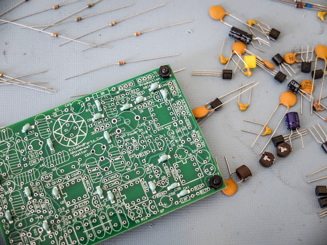
The Universal 1Watter (also called the 1H2O) is a full featured little superhet radio transceiver that you can build for about $50. It doesn't come with an enclosure, a tuning pot, speed pot or an on/off switch so that will cost extra unless you already have some in the junk bin.
Some of the features include;
1 mighty watt of output
Good selectivity from the 3 crystal filters
A VCXO tuned frequency range for the 40m band from approximately 7,020 kHz through 7,039 kHz
A built-in full functioned keyer with provision for adding a speed pot and messages
Included command button accesses the functions of the electronic keyer
Natural sounding sidetone (nicer than my Ten-Tec Century/21)
The Build
The kit is delivered in a box and inside are a couple of brown paper bags stapled together. Inside one of the bags are a couple of plastic bags with the components. The other bag contained the header kit. The ferrite toroid mix types are separated in different unmarked plastic bags so don't mix them up (the instructions tell you which bag has each mix). If anything is missing the kit supplier (Diz, W8DIZ) is very responsive.
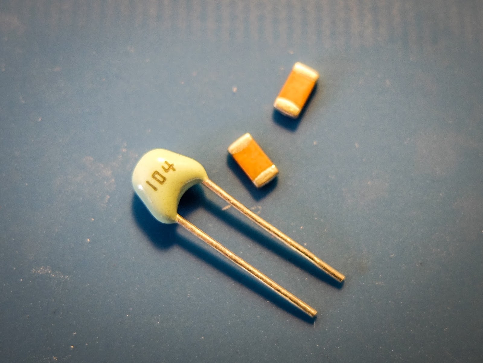
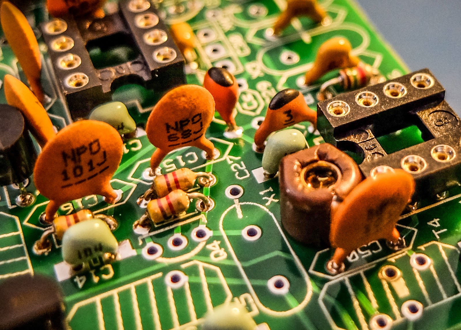
The kit includes both SMT caps and through hole caps. I tried to solder one of the SMTs but I didn't have the right kind of tweezers to hold it in position for soldering so I used the through hole caps.
SMT and through hole caps are supplied
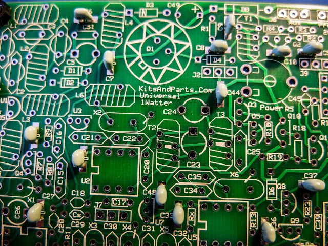
This is the 3rd revision of the Universal 1Watter board and I was the first to build the 40m version.
While the schematic was correct, some of the instructions weren't sorted out properly for the 40m kit. I related issues as I found them to the designer and he promptly updated the online documentation.
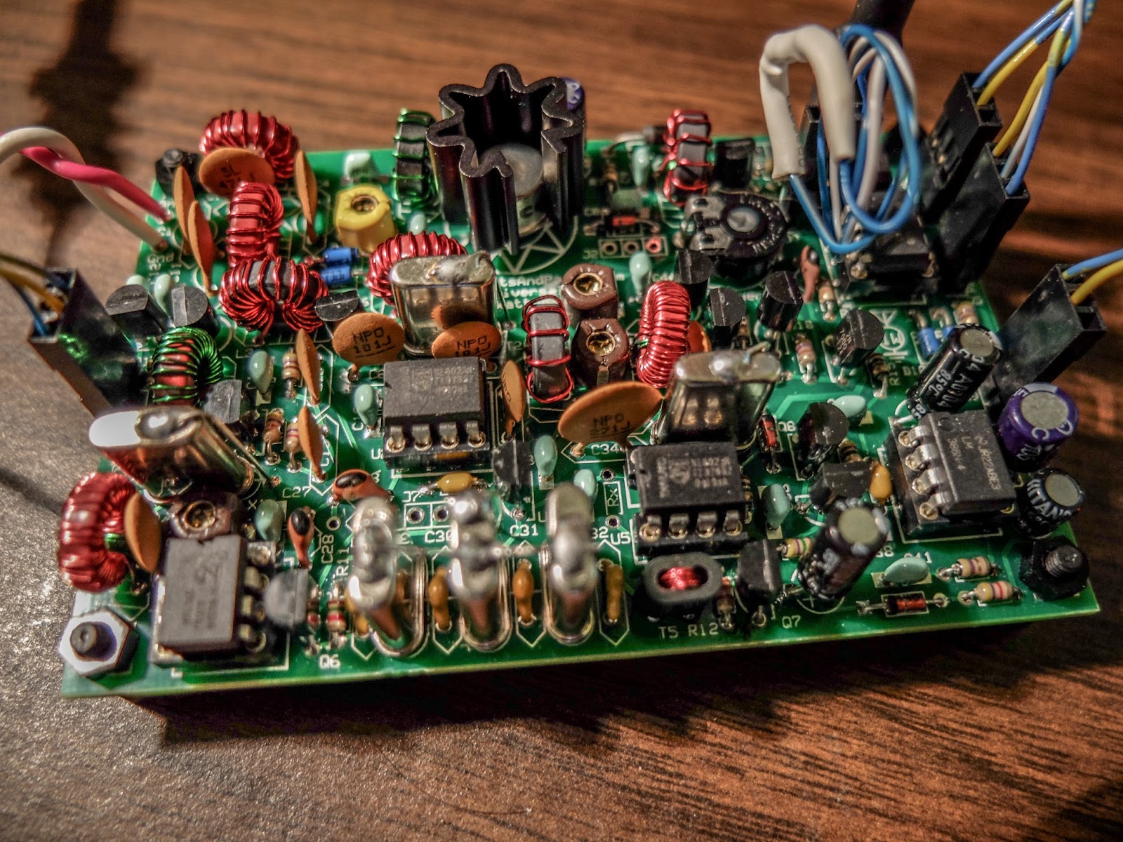
I soldered the components and wound toroids as I had time over a few evenings and the initial voltage tests went well.
using through hole capacitors rather than the SMTs
some of the bits and bobs
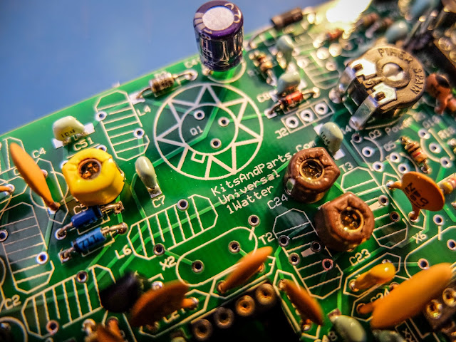
build is progressing
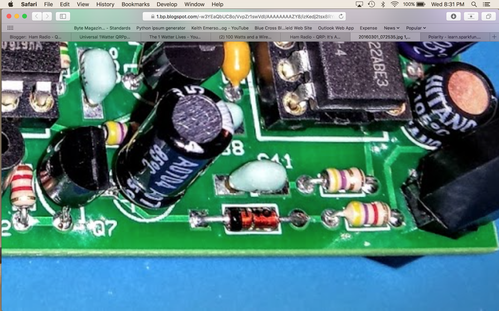
close up
XTAL filters give it good selectivity
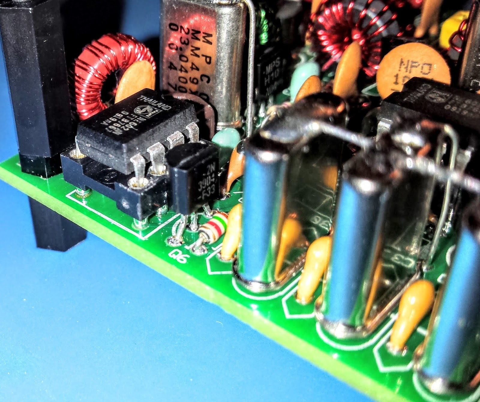
Everything except the final transistor
AGC circuit
Debugging
When the build was completed I connected the rig to an antenna and heard nothing.
The keying circuit and transmitter worked fine and I verified those functions but the receiver was deaf as a stump.
Thus began a number of days of investigation. Diz (the creator of the board) guided me through a number of debugging steps.
The first recommendation was to examine and rewind the binocular toroid balun that transformed the impedance from the xtal filters to the input of the U5 oscillator. He believed that I may had wound it incorrectly. I desoldered it and rewound it but that did not resolve the issue.
He then guided me through determining if one of the filter crystals or filter capacitors was bad. I desoldered a few components as a tests but that did not resolve the issue.
There are 3 identical mixer chips on the board. I swapped them around as there was a suggestion that there were some faulty chips in one of Diz's shipments.
I then took the board to my Elmer Paul Stroud AA4XX. He had a signal generator, Oscilloscope and RF detector. He traced the RF and all looked well but we still were unable to obtain any signal through the U5 mixer. Lastly we tried disconnecting the AGC transistor to see if it was clamping it and that didn't resolve it either.
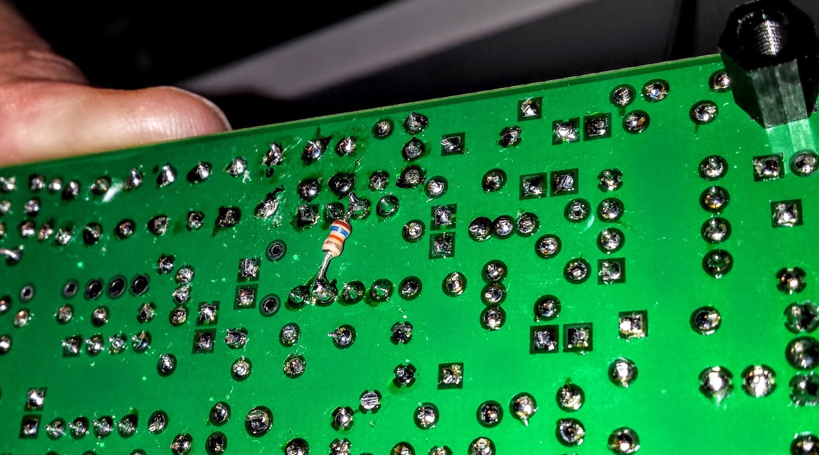
Diz asked me to return the radio to him so he could take a look. After a couple weeks he emailed me saying he thought the BFO xtal might have a problem. But he later discovered that the oscillator in U5 was not starting up. Apparently the circuit design had a low Q and needed more current to get the oscillator working. He modified the design, adding a 16k resistor to the bottom of the board on U5 to get the oscillator going. After that all was well and he shipped the board back to me.
The FIX for all those problems required an extra resistor connected across U5
Learning from problems
Being the first person to build a particular version of a kit brings its own set of challenges, especially when you're as new to kit building debugging RF problems as I am. However I'm actually glad the kit didn't work right at the initial build. The process of debugging the board, was a great learning process. I studied the schematics and learned, as best I could, the function of each circuit so that I could better understand how to test it. During the debugging process Diz instructed me that although RF signal generators and scopes are useful you can tell a lot by touching a RF component with an inductive metal object and listening for a buzz or hum from the BFO. So all-in-all, even though the bug in the board was not due to a error on my part, I'm glad it occurred. I understand more about superhet radio design than I did before and more than if the kit had worked right off the bat.
On the air
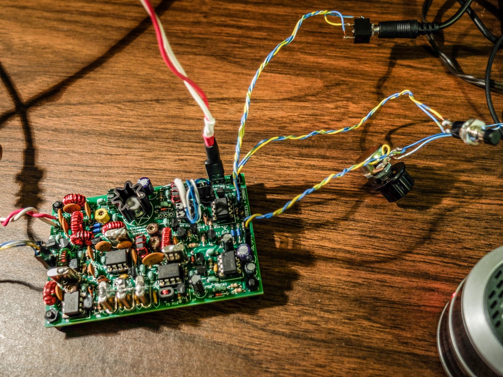
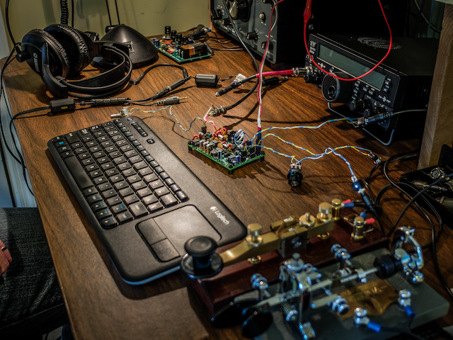
After receiving the board back, I hooked up the frequency XCO potentiometer, paddle, command button, audio and output potentiometer and an external speaker. I then connected a 12v battery and heard the 1H2O keyer chip announce itself at power up in Morse "1 W".
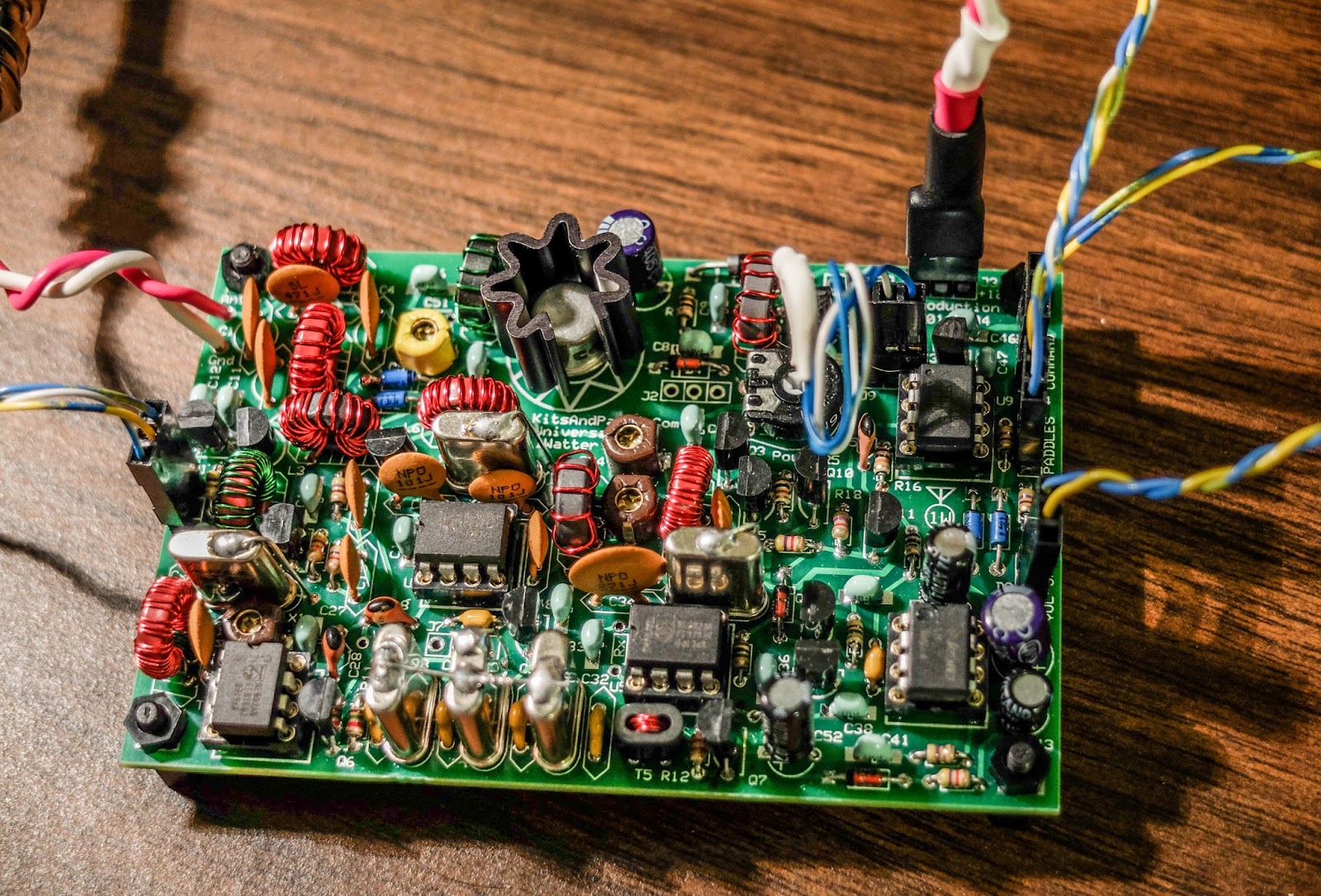
Frequency control pot on the left
Volume control, output jack, cmd pot and paddle input
You can change speeds and modify settings via the command button which I have not reviewed yet. I also plan to add the speed pot so that I can easily change keyer speed without entering the command menu. For this first on-air excursion I was using it at the default startup 15wpm keyer speed. You can default the speed higher with a different resistor value. I have a resistor shrink wrapped and connected in-line to the blue-white wire coiling above the radio connecting to the speed pot terminal. In essence fixing the speed at 15wpm until I add the speed pot.
Ready to transmit
On the air... I was using my paddle out of the photo to the right of the Bug
First On Air QSO
I tuned around and found a strong station at the end of a QSO near 7030 kHz.
When he sent the final dit-dit I called and WD4AXJ answered my first call. He was in TN near Knoxville, and I received a 559. We chatted for about 10 minutes. Sorry about the blurry video. I thought I'd focused.
After I recorded this video I found an open frequency and sent out my call. Very shortly thereafter KD2FSHanswered my call and reported me as 599!
Whoo - hoo. 599 for my little 1Watter 40m.
I was transmitting using my 40m attic antenna. So deed restricted HAMs take note. You can build a one-watt radio and make contacts using your attic antenna. Haha.
You'll hear in the video there is some weirdness going on with the audio derived AGC. It is clamping down sometimes and is worse when I don't have the volume turned up very loud. When I began calling it clamped after every semi-break-in but didn't do it much after that. I'll have to look into that.
The AGC clamping may be a side effect of the increased gain Diz added to the BFO oscillator. I'll ask the forum.
Other than the AGC issue I'm super pleased with the little board. I touched the heat sync a couple of times after transmitting my side of the qso and it was warm but not really hot. It seems as though as long as you have a reasonable match to the antenna the power transistor should be happy.
My next steps are to get it in an enclosure and get it out to the Excalibur antenna site to hook onto that nice 40m doublet we put up a couple weekends ago. I plan to use my efficient little BLT tuner for that purpose. I will do a further review of the feature set on the keyer and record some more qsos for a later review.
Summary
The band was fairly busy and the little 1Watter did a fine job with stations on nearby frequencies. You can hear some getting around the passband but it is not bad at all. I'll do some tests to further define it's selectivity but at first glance it is far better than my old Ten-Tec Century/21.
My calls were answered quickly and I received good signal reports. It didn't sound as though the transmitter was drifting at all during the QSO. That's one advantage of using VCXO in the design. The disadvantage of using a crystal controlled oscillator for the frequency control is limited tuning range. The transmitter only has about a 18 kHz tuning range around 7030 kHz and I don't find many of the SKCC folks around that frequency but it is the QRP watering hole for 40m.
It is possible to shift the frequency with some capacitance changes but I think I'll leave it as is for a time and see how many states I can work.
Just imagine. This little $50 single band kit has good selectivity, a nice built-in keyer with a natural sounding sidetone, and lest we forget... You get a MIGHTY 1 WATT of OUTPUT. What more could a QRP ham need.
That one-watt of output was sufficient for all the QSOs I attempted tonight.
So lower your power and raise your expectations
72/73
Richard, AA4OO
UPDATE: 04/01/2016
I
am still having the AGC pumping issue and others on the list have
reported similar issues but only on receive. It happens to me when I
key unless I turn up the volume very high. I did get it installed in a
case but I still need to wire up a real power connector rather than
using alligator clips.
!Watter installed in a case
UPDATE: 04/05/2016
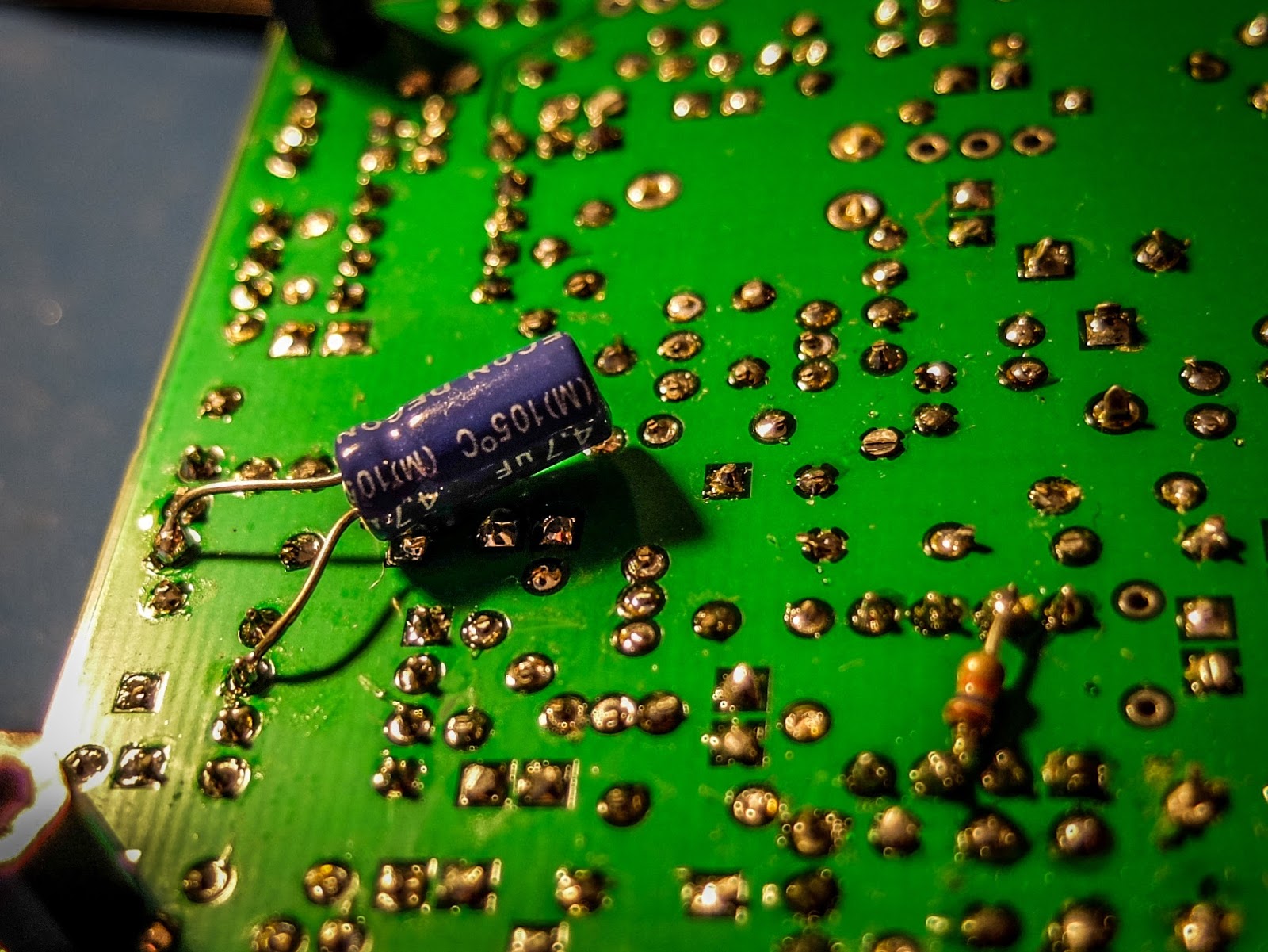
After doing quite a bit of reading I learned that the LM386 op-amp used in the 1watter
is rather notorious for audio oscillations. There are a number of
suggested fixes. I went with a 4.7uf cap connecting Pin 7 on U6 (the
LM386) to ground. That hasn't totally resolved the issue but it's much
less pronounced now.
cap fix for LM386 oscillations
I
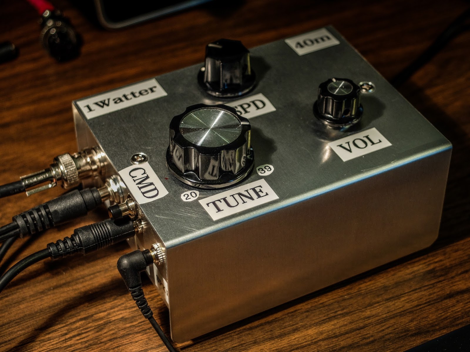
have it in the case with all the proper plugs now (see below) so I'm
happy. I've been making QSOs every day with it and it continues to
amaze me and the stations that work me. It is stable as a rock with
regard to frequency and the large knob with the single turn 10k pot
seems to work well for tuning. I have enough control to vary the
frequency slightly without having to turn it too much. The tuning range
is only about 20kHz so just 3 frequency markers are plenty to let me
know what frequency I'm near. The selectivity is just fantastic for
such a simple little radio. Diz has created an inexpensive winner.
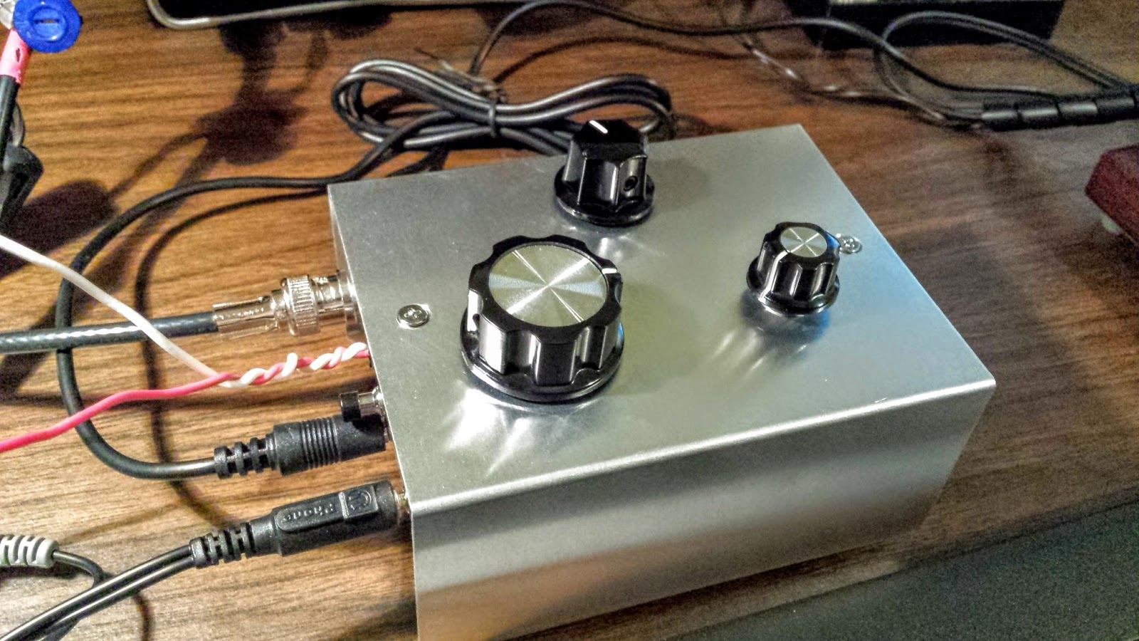
1Watter in enclosure with all the proper connectors for the case Information on case and knobs:
I've had the opportunity to bring another wonderful radio from Ten-Tec into the shack. The Ten-Tec Eagle.
Ten-Tec Eagle HF transceiver
The Eagle is NOT a feature laden radio and using it is a bit quirky.
There are no menus on the Eagle. The dual-function buttons you see are what you get. The multi-knob allows adjustments for the various functions.
What it does have that is so common with the Ten-Tec line of radios is absolutely wonderful sounding audio and beautiful full QSK with no strange audio artifacts at full-break-in. It is a pleasure to work weak stations. This particular radio has three 4-pole filters for the IF at 2.4kHz, 600Hz and 300Hz. They are automatically selected as the dedicated bandwidth knob is adjusted, resulting in smooth and clear filtering of CW stations.
I also have a Elecraft KX3 and while it has similar receiver specifications, listening to weak CW with it has a lot of digital artifacts that are not present on the Eagle. I can work a weak station with the Eagle and not be fatigued at the end of the qso.
It also has a nice ATU capable of matching up to 10:1 SWR antennas and of course supports SSB. It covers 160m-6m and can do FM if the 15kHz filter is installed.
Eagle beside its much older brother, the Ten-Tec Century/21
CW the way it was meant to be heard
The solar conditions have been extremely poor over the past week that I've used the rig and are likely to be this way for a few years to come. It's nice to have a rig that makes these poor conditions still enjoyable.
If you love CW do yourself a favor and try a Ten-Tec. They are pricey compared to other rigs and they do not come close competing on price-per-feature but Ten-Tec receivers make for amateur-radio bliss.
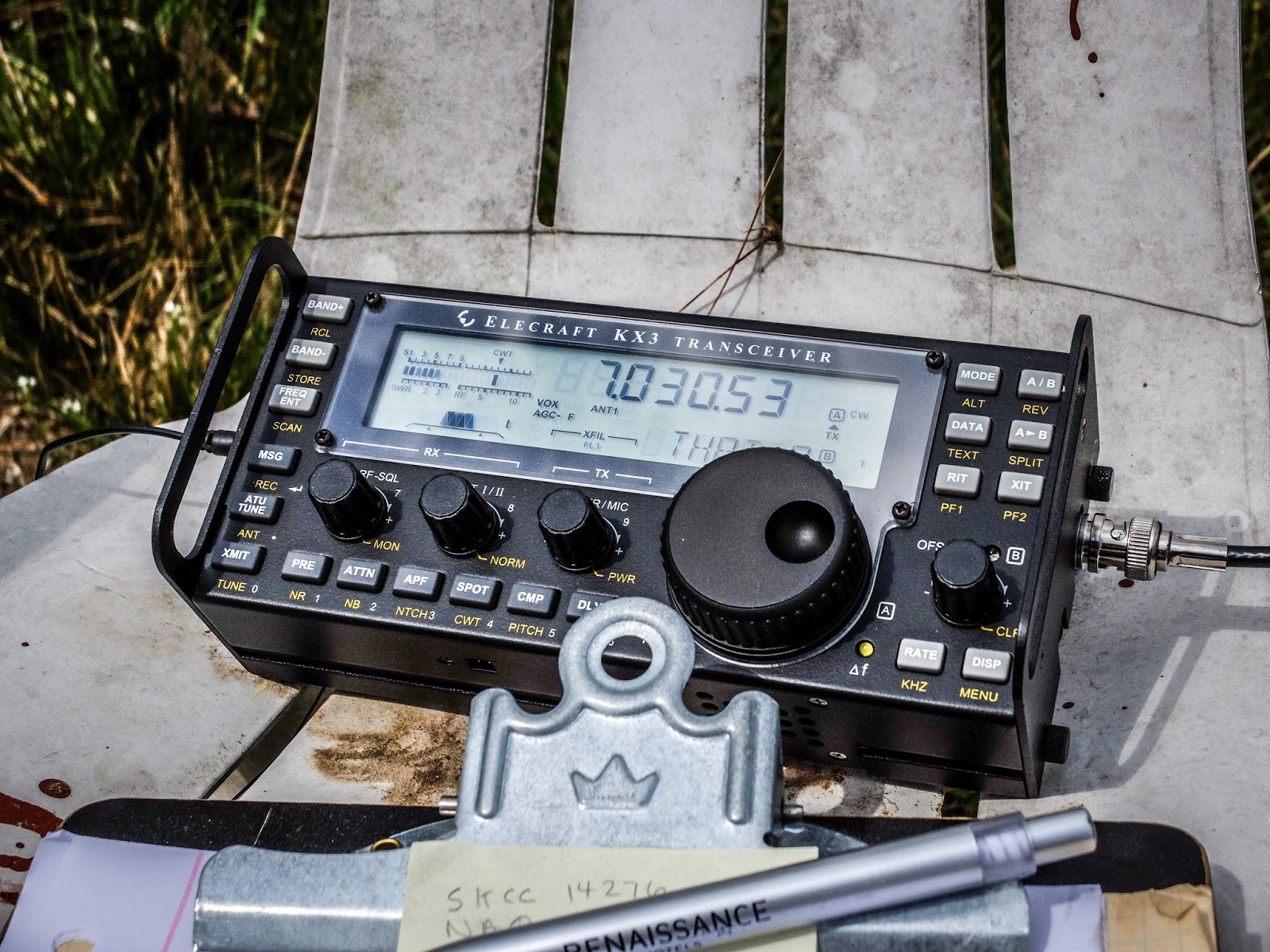
KX3 operating on internal battery. What a fantastic portable rig.
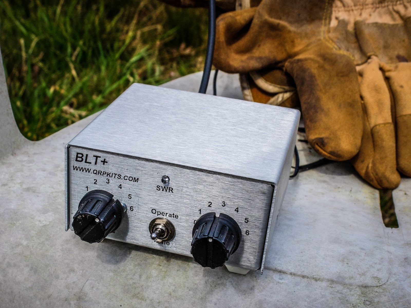
I took the BLT+ balanced line tuner out to the Excalibur antenna site to try it out on the doublet antenna that we put up last Saturday. This was the first test of that antenna (40m and 80m using a common feedpoint).
I didn't have much time today and after the first QSO it started to rain so I packed up and left before getting as much documented as I would have liked. I apologize for not recording the actual tuning process and the subsequent QSO.
BLT+ connected to open wire line (under the gloves) going to ta 40m Doublet at 65ft
I had the KX3 operating using its internal batteries and outputting 2w. I was running 2 watts because that is the most efficient PA mode for the KX3. I used the BLT+ to tune the 40m/80m doublet. Balanced line antennas perform better with a tuner designed for balanced line and this was a good test for both the tuner and the new antenna.
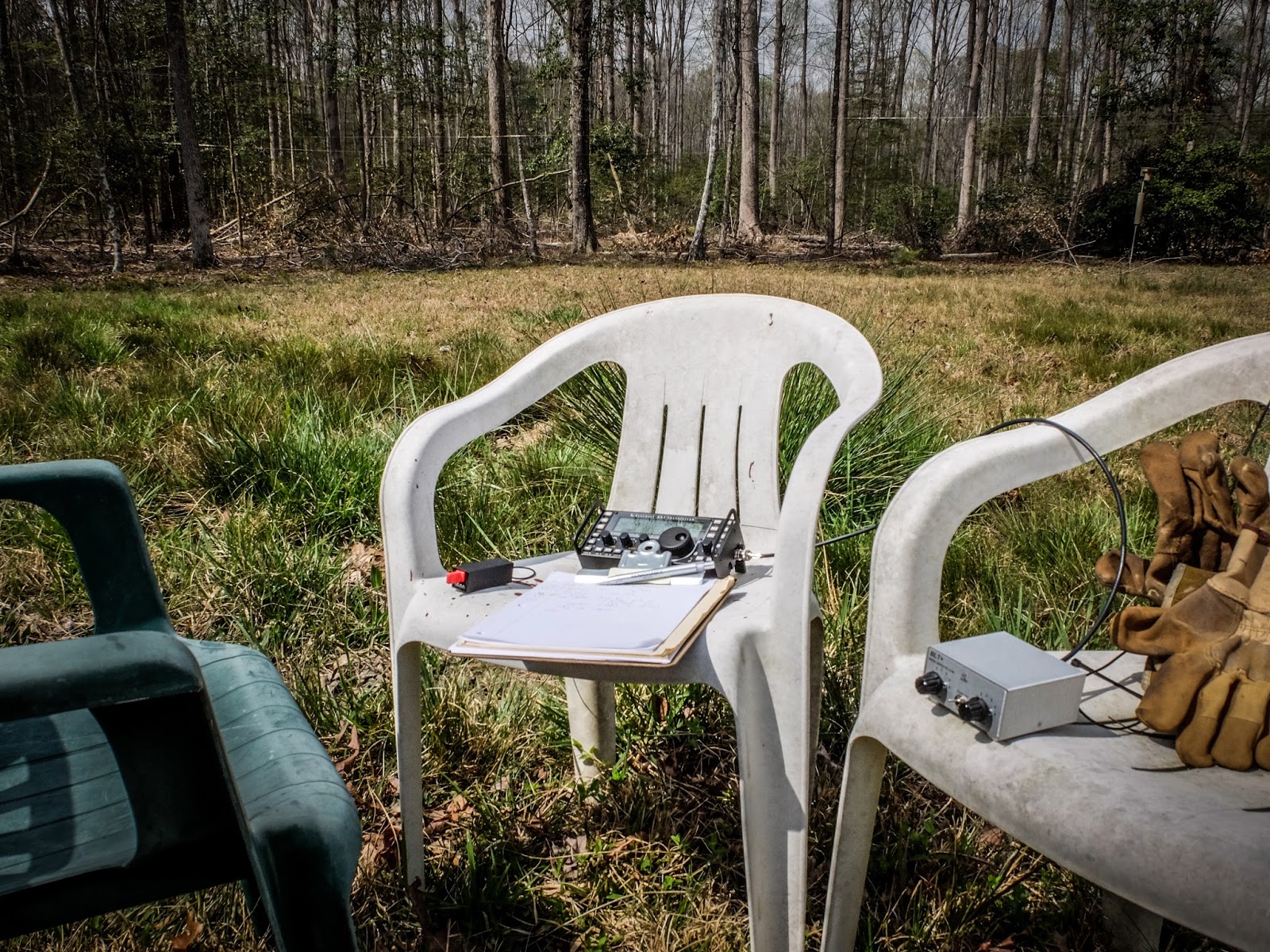
Portable shack, courtesy of three plastic chairs
I quickly matched the doublet using the BLT+ using the lowest impedance setting which is also the most efficient. I was glad to see that the BLT SWR LED indicator is bright enough to be seen in direct sunlight. I was wondering about that but you can definitely tell when it dims even in direct sunlight.
Performance
After quickly tuning up I sent my call two times and was promptly answered. The other station was running a Flex 6500 into a KPA500 and a OCF Windom at 50 feet.
He reported me as 559, while he was a 599. He was running a new KPA500 amp at 500w so we were a bit mismatched on power.
Interestingly the difference in 2w and 500w exactly matches the 4 S-Unit difference in our reports if you do the math (each increase in an S-unit requires quadruple the power).
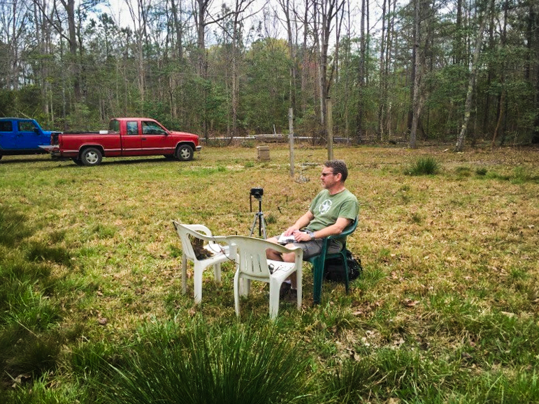
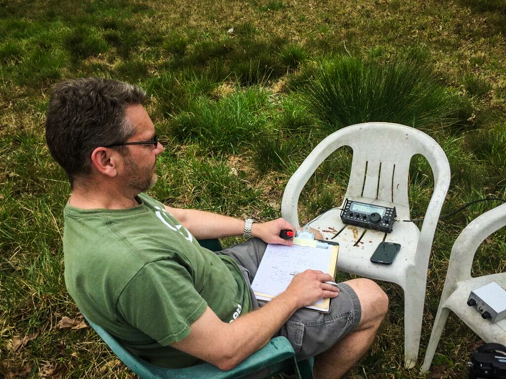
AA4OO sitting back and listening to the QSO
Paul AA4XX kindly snapped some pictures while I was listening to the other operator. This is the Excalibur antenna site but the shack is outside the photo. The Doublet's feed line has not been brought to the shack yet so I was just sitting under the antenna. The open feed line is running along the ground for a bit which certainly didn't help the signal but we haven't installed the posts to carry the feed line over to the shack and I was too lazy to move the chairs far enough away to keep the feed line in the air. In the foreground is some saw-grass common on the NC coast. I'm not sure why it's growing this far inland.
Portable shack at the Excalibur antenna site... The Doublet is 65 feet above my head
Waiting my turn in the QSO... holding the Palm Single Paddle. BLT+ tuner in the chair to the right
Video
Here is a brief video showing how the BLT+ is connected to the Doublet...
Summary
The little BLT+ performed great with both balanced line antennas I've tried. It is easy to use and allows me to use my KX3 with balanced feed line antennas now. I encourage you to build the kit from Pacific Antenna / QRPKits.com .
Last Saturday morning was cool and damp. What better outdoor activity for such a time than putting up some antennas.
I had the opportunity to help put up an 80m/40m Doublet at the Excalibur antenna site. My only previous experience at getting antennas in trees was to use a throwing weight with kite line, but Paul Stroud (AA4XX) showed me the finer points of using a slingshot.
Up, Up and... well that didn't go where I aimed
Getting an antenna support through the top of an 70-80 foot tall tree is a multi-step process. Or if you're new at this like me and miss your mark with a slingshot, a repetitive, multi-step process.
Attach a fishing reel with lightweight 6 lb fishing line to a slingshot. Lubricates the line with a very lightweight oil or teflon to let it better slide over branches, especially in the spring when the sap starts to flow.
Attach a 1-2 oz weight to the line with a snap hook. You'll be taking that weight on and off the line frequently.
Sight well above the tree and aim for a hefty fork in the branches that you wish to support the antenna wire.
Let it fly... At which point there are a couple of possibilities:
If you are Paul and you've done this many times then you move on to the next step.
If you're like me you miss badly a few times, or you tangle the fine fishing line on the launch. When you miss:
Gently tug on the fishing line watching for where the weight is at the other end. Mark that spot in your mind.
Go detach the weight, come back to the rod, THOU SHALT NOT try to reel the line back with the weight attached. If you leave the weight on while trying to reel it back IT WILL wrap itself around a branch and you'll have to cut the line and likely lose the weight.
Reel the line back in and try again.
Gently tug on the fishing line to find the weight at the other end bobbing above the ground so that you can find it.
Go to the end of the line that you marked in your mind (you were paying attention weren't you?) and detach the weight and attach 100 lb fishing line to the 6 lb line.
Reel back your 6 lb line now bringing with it the 100 lb fishing line.
Attach your antenna rope (or weedeater line in our case) to the 100 lb fishing line, go back to the other side of the tree and pull it through while re-spooling your 100 lb line. Getting the heavy line through the branches requires a bit of tugging.
Now attach your antenna to the support line and prepare to repeat the steps for the other side of the wire.
Correcting one of my many blunders. Homebrew ladder line in the foreground.
In our case we had a 40m dipole and 80m dipole attached to the same insulator so we were raising one antenna with 4 ends. Ultimately the center feedline height was about 65 feet with the 80m and 40m antennas about 30 degrees off axis from each other. The 40m antenna was aligned for best propagation to Europe. The relatively low height of the 80m antenna meant that it was omnidirectional. The feedline was 125 feet of home-made open wire feedline made from cheap insulated 18 gauge wire and electric fence insulators. The plastic electric fence insulators had a hole drilled in each end and small zip ties were used to hold the wire in place. Insulators were spaced approximately 18 inches apart on the feedline. That's a lot of insulators. Paul is a patient man.
Other work at the site
While Paul and I were working to get the 80m and 40m doublet raised Dick (N4HAY) was doing an inspection on the antenna mounted on the 75 ft crank up tower. The tower had been lowered for maintenance.
Cranking it back up is a good cardio workout.
N4HAY displaying the proverbial "High Standing Wave"
So I'm learning about raising wire antennas and sharpshooting with slingshots. Fun times.
I wanted to test the BLT+ Tuner portable with a ladder line fed Doublet but my time has been limited. After getting home from work one night I assembled a 40m Doublet fed by 450 Ohm ladder line in my driveway.
I pushed the Doublet up on my Jacktite pole and attached the ladder line to the BLT+ and attached the BLT to the KX3. I had the KX3 sitting on the deck table running on internal batteries.
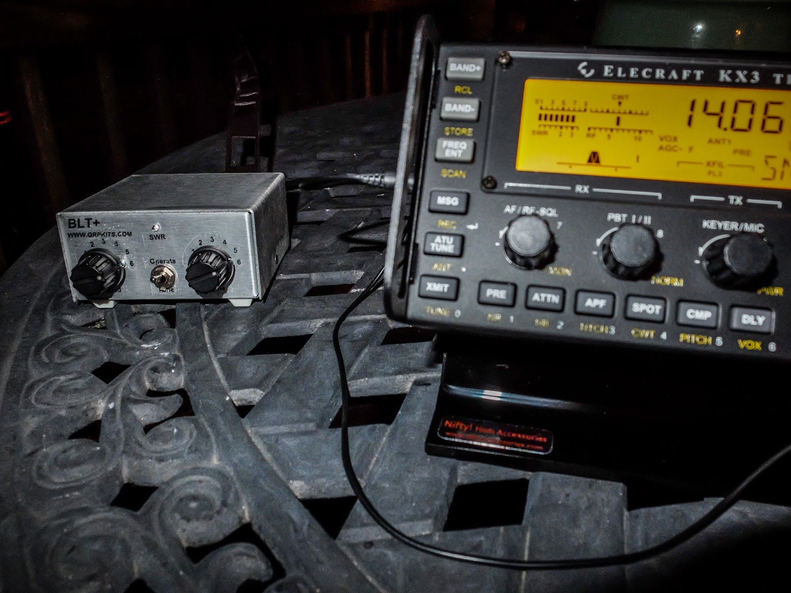
BLT+ tuning the balanced line antenna
By the time I began my test it was quite dark except for the moon. My headlamp was out of batteries and I was operating by a floodlight up on the eve but I was determined to know how the tuner worked with my portable doublet.
Doublet on Push up pole. Moon in the background.
40m and 30m tuned up 1.0:1 using the high capacitance setting. Tuning was fast for each band using the SWR indicator LED. After tuning on 7030 and sending my call then again on 10110, I tried 14060. Although tuning 14m was a bit touchy it tuned using the low capacitance setting to around 1.5:1 SWR. After tuning I sent my call on 20m. Immediately I received a call from K7JHM, a QRP station in Utah (about 1700 miles away). We exchanged signal reports and station information although copy was a bit rough. I'd neglected to bring my earbuds out and the speaker on the KX3 is pretty poor.
However, the QRP to contact was a success on a portable antenna, tuned with the BLT+ driven by a rig running on internal double A batteries.
I didn't try higher bands because it was so late in the evening so I packed it all up declaring success.
Balanced line tuner doing it's job
Tuning 20m was a bit touchy because my total length of one leg of the doublet plus the feedline is too near a 1/2 wavelength on 20m. I need to add about 7 feet of ladderline to keep it from being near odd 1/8 wavelengths of the bands I want to tune. Or I could add 7 feet to each leg of the antenna. I will need to do that before the next test.