Showing posts with label aa4oo. Show all posts

Thursday, February 8, 2018

HP-23 upgrade board kit from Old Heathkit Parts

Breath new life into a Heathkit HP-23 power supply

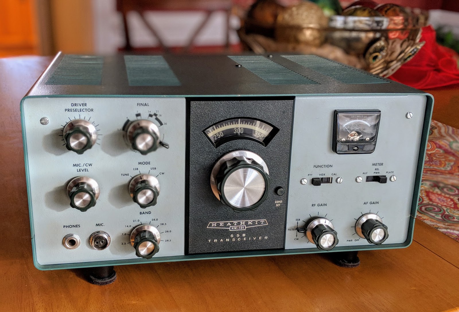
My recent interest in restoring a 1970s Heathkit HW-101 tube radio, is leading me down quite a winding path. 

Before I can even test the HW-101 I must be able to supply it with power.  Vacuum tube radios need multiple voltages for the different tubes in use.  In the case of the 20 vacuum tubes used in the HW-101, it needs the following voltages to operate, 800v, 350v, -130v and 12.6v.  

If you've followed previous posts you'd read that I thought I'd be clever (as if), and restore a Heathkit power supply that runs off of 12v so that I could use it mobile or from my 12v linear supply in the shack.  Well, I restored a HP-13 and if you read that post and watched/listened to the video you and I now both understand why operators only used those power supplies out of earshot, like in the trunk of their automobile, or in the next county.  It makes way too much audio racket to be at my operating position.

So, pouring a bit more money into this effort, I bought a AC/mains powered supply; the Heathkit HP-23B... but alas it has old components and also needs to be restored.
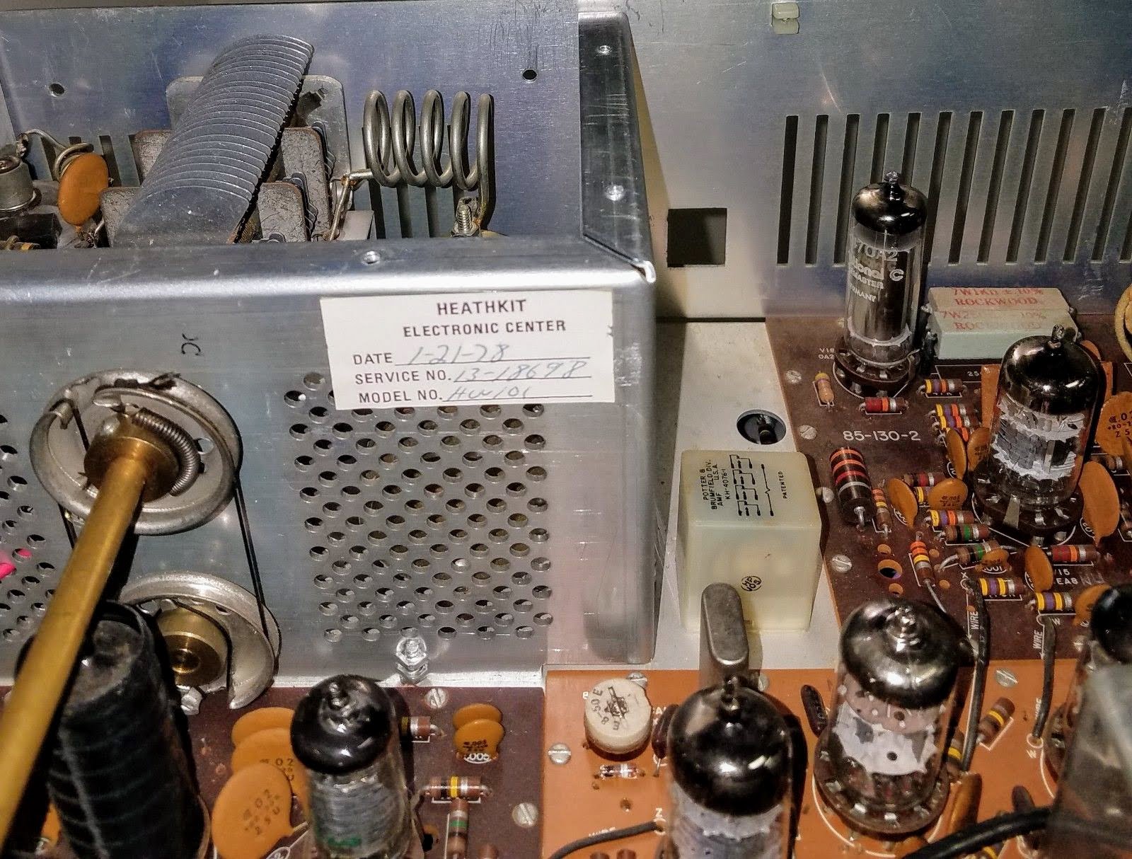
Heathkit HP-23B

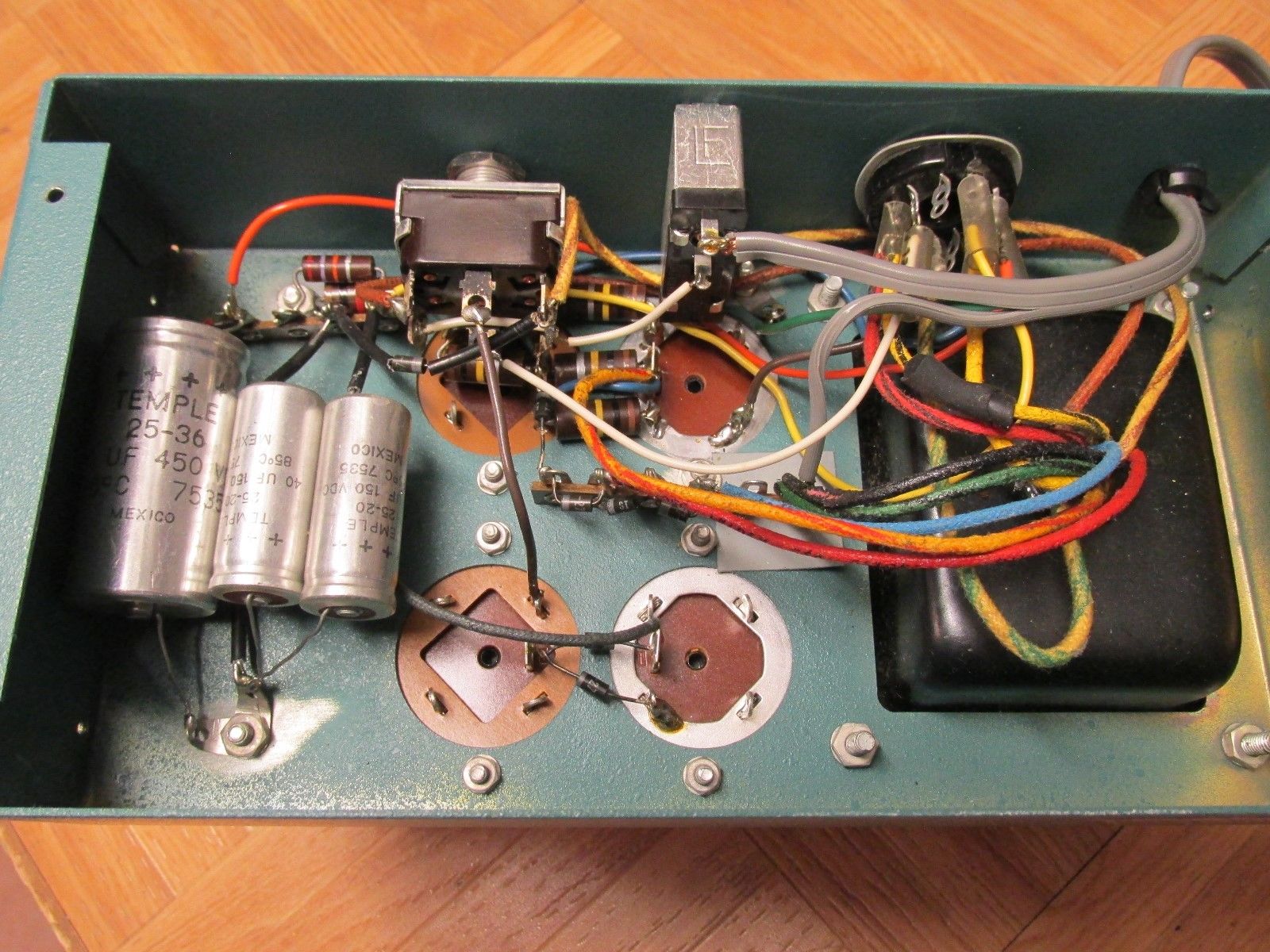
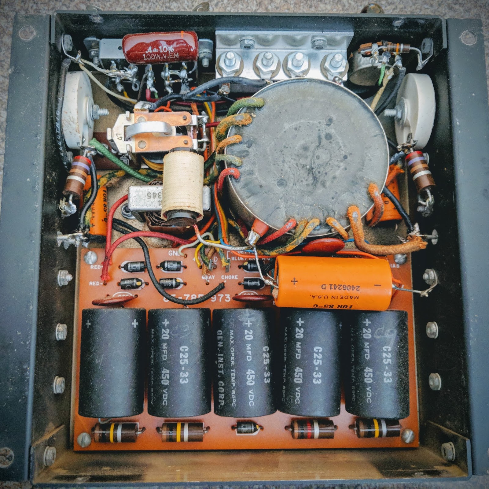
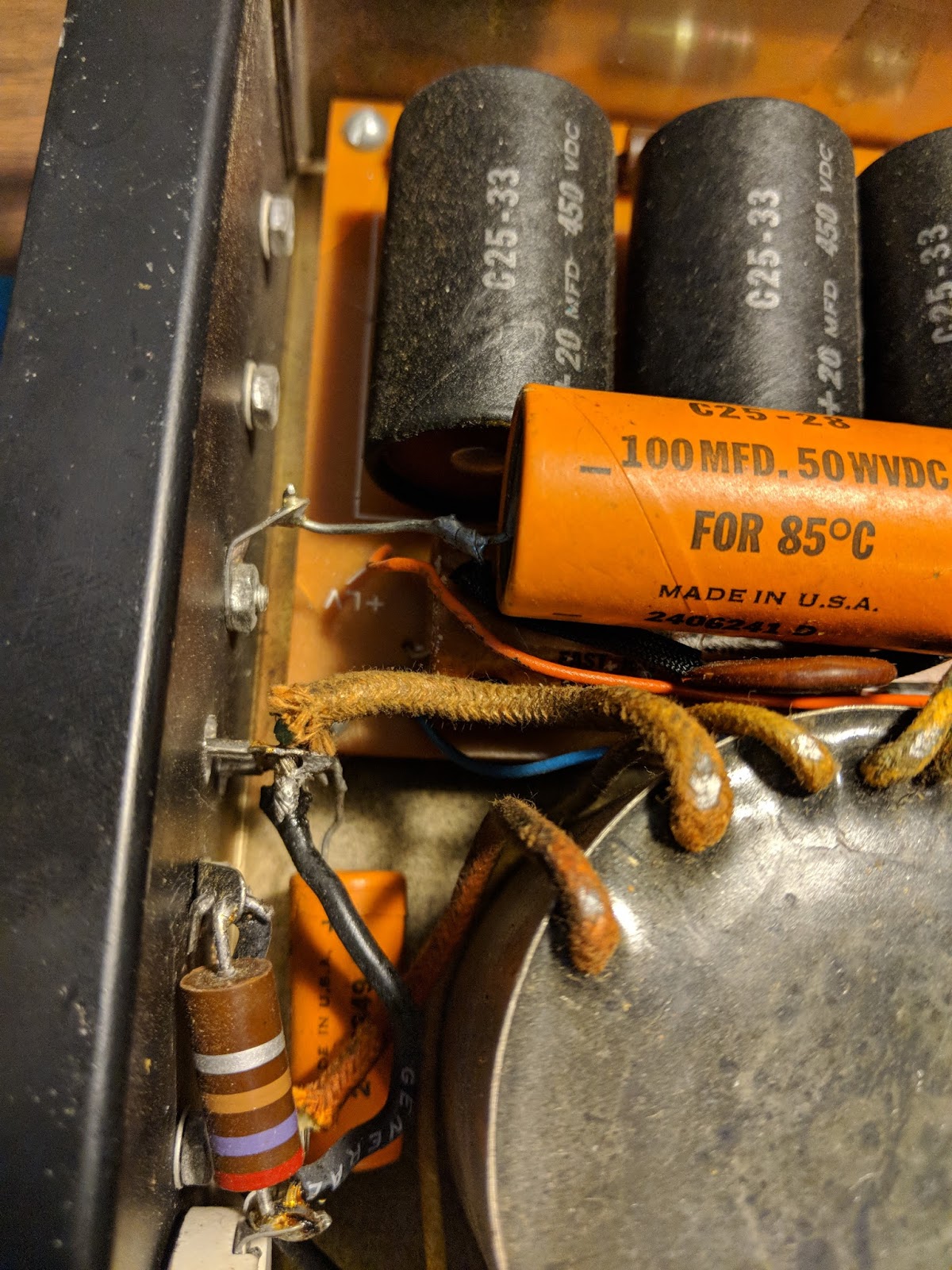
No direct replacement capacitors

Those large capacitors in the first photo have no modern equivalent in terms of the pin-outs and the HP-23B chassis used some phenolic wafers that are rather fragile after this many years, to hold those capacitors.  There are some videos showing how to adapt modern capacitors to fit and that would help maintain it's classic look, but it seemed a bit fiddly to do.  Also, you can see that in the base of the power supply there are numerous other axial caps and resistors that need replacing and it's a frightening mess of wiring in there given the voltages present.

Old Heathkit Parts to the rescue

This is such a common issue with these power supplies, that K8GNZ designed a PCB compatible with modern electronic components that would replace that tangle of wiring.  It can be ordered from Old Heathkit Parts for a reasonable sum and comes with a CD listing the components that need to be ordered as well as instructions for building the PCB and wiring it up with the HP-23B.

This board gives you one convenient place to populate all the components and hookup the wiring in the HP-23 chassis.


HP-23D PCB

The 3w 100k resistors go on the bottom mounted 1/4" off the board so they don't burn the board (they get hot)

Partially populated board

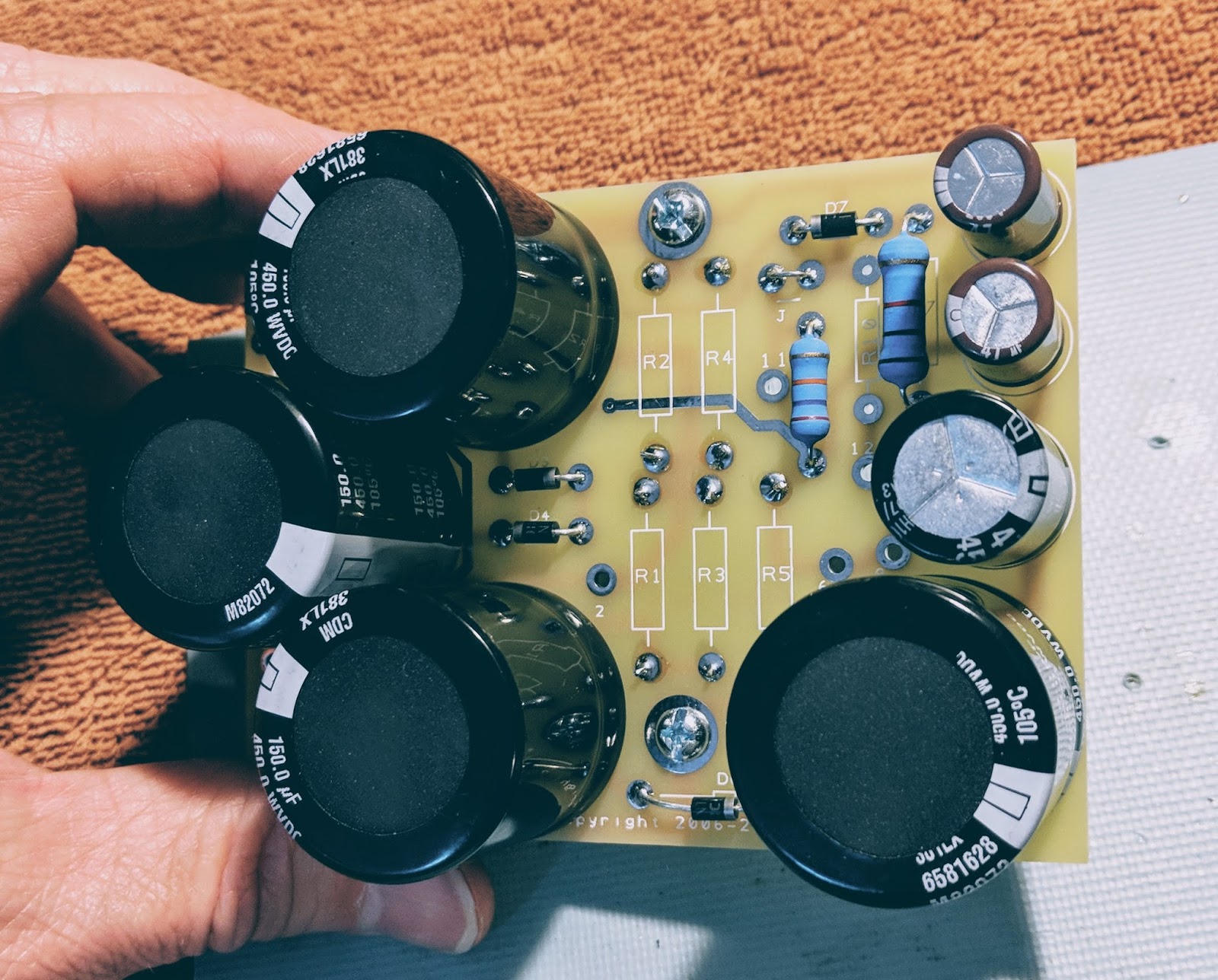
All done, ready to wire up to the HP-23 transformer and choke

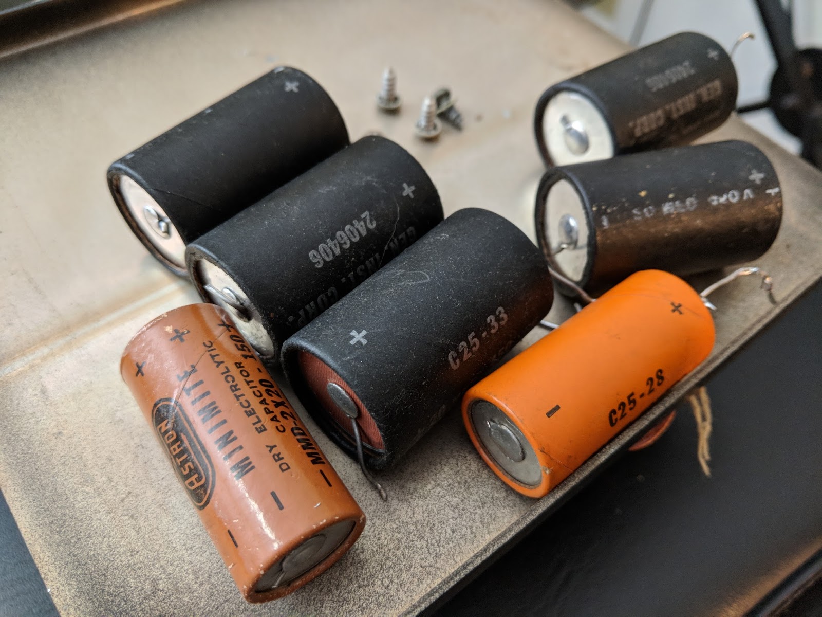
Note how much smaller the 4 new 450v caps are than the ones they replaced in the photo at the top of the post.

The next step is to tear down the old HP-23B and prepare for this board to replace its innards.  Maybe this weekend.

Gotta get the power from the supply to the radio

The power supply has 8 connections to the radio and Amphenol 11-pin plugs are used for the connections.  I purchased a wiring kit on eBay that I'm not really pleased with so I won't provide a link to the seller.  It works but there were some compromises.  If I need another cable I think I'll just find a used one.
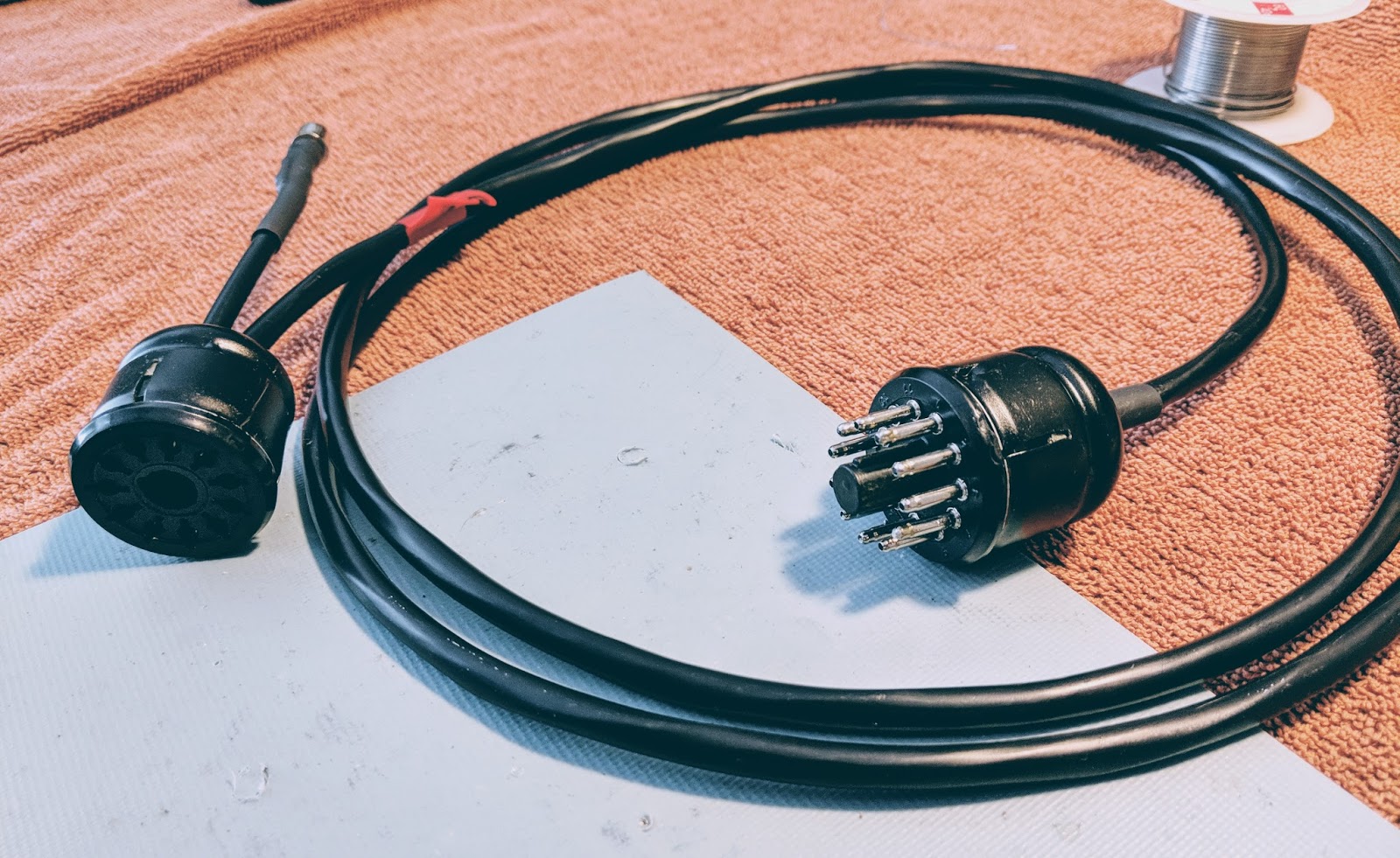
Power cable

I also added an amp-key line out from pins 5 (ground) and 11 (relay) for future projects.  I terminated it into a female RCA plug.  I have previously used the amp-key line from my Ten-Tec Eagle to trigger the protective relay on my SDR, so I may use it for that, or something else.  I figured as long as I was soldering 16 connections in those plugs I could solder a couple more.

Amp-key line out


I've also purchased an additional NOS female Amphenol 11-pin chassis plug that I plan to wire up from the Grove connector on the HP-13 so that I can just use the HP-23 cable with the HP-13 if I wish to in the future.

So just a few more hours of work and I should be able to light up the old HW-101 for the first time in decades.

The smell of hot tubes awaits...  or magic smoke...  I hope it's the former


That's all for now


72/73
Richard, AA4OO

Friday, February 2, 2018

Noisy power supply -- Heathkit HP-13

Resurrecting a Heathkit HP-13

As seen in my previous post I've taken the dark plunge into the world of tube radios.  I want to start restoring my Heathkit HW-101, but before I can do that I must be able to power it.  As I previously wrote, I taken the road less travelled and got an old (circa 1965) HP-13 mobile power supply because I thought it would be nice to power the radio from a 12v source rather than mains. 

Unrestored HP-13 with broken solder joints and trashed capacitors


Well there seems to be a reason these don't seem very popular... I'll get to that.

I found a very nice article from RDF-Electronics regarding modernizing the HP-13 power supply.  That document includes the components and part numbers for everything you will need to restore your HP-13.  My parts arrived from Digi-key and I began snipping and desoldering the old component off the PC board.  The replacement electrolytic capacitors are all much smaller and have radial rather than axial leads.  That makes placing things on the board require a bit more creativity.  

HP-13 Schematic

The only truly problematic components to replace was replacing the twin positive axial lead electrolytic (C11) with two electrolytic capacitors (space issue) and replacing the C1 and C12 due to the tricky wiring around the transistors. 

The orange cap on the left under the Q1 (C1) was tough to replace with a much smaller radial lead capacitor

The article suggested replacing the original 100 uF/50 V capacitor with a 4,700 uF/35V to better control ripple.  The article goes into quite a bit of detail concerning his testing of ripple using an oscilloscope.  Finding room for that big cap and it's accompanying filter disc required a bit of creativity as seen below, where it's laying on its side between two of the rectifier caps.

I will glue all the caps to the board before I put the power supply into service.


New capacitors and diodes

I replaced all the electrolytic caps and diodes.  The diodes might have been ok but they are blocking over 300 volts each and a single failure would let the smoke out for sure.

Out with the old

In with the new
All the resistors except one 100k 2 watt were ok.  So I only replaced that resistor.  The 1.6kv disc caps even measured ok.

The internals look a bit different now with the new caps standing up where the old, larger axial lead components laid flat.

Ready for testing

Testing

After performing resistance and continuity checks I buttoned it up for the test.

The Noise

I had no idea how audibly noisy this power supply would be.  The switching that occurs in the transformer creates a very loud whine.  I understand why hams would install these in the trunk.  There's no way you'd be able to stand this for long if it was sitting next to your station.

I have a longish intro in the video.  Skip towards the end to hear it powered up... turn your volume down when you see the "hearing protection" sign come up in the video.


Conclusions

This was a good learning experience.  I learned about high voltage transformers and got some practice restoring older equipment.  I practiced electrical safety and didn't kill myself, so I'm pleased about that.

I now have a power supply I could use from a sturdy 12v source if I needed it, BUT due to the noise in operation I'm going to look into restoring a HP-23 which runs off house mains (AC) and is mostly silent. 

I'll keep this on the shelf waiting for a day that I need to run the HW-101 mobile. 


That's all for now

73
Richard AA4OO

Saturday, January 27, 2018

Before transistors there were TUBES

Oh Boy, what have I gotten myself into

TUBES

A few months after re-entering the hobby in 2015 I picked up a TenTec Century/21.  It has been one of my favorite radios to operate and it is the most aesthetically pleasing radio I own.  After working with it's older (circa 1977) discrete transistorized technology and debugging some of it's problems, I became interested in building kits to learn about electronics.  I built a number of radio kits from different sources and some of the mini-module kits from Elecraft.

But I kept wondering about tube radios.  I came to the hobby well past the tube radio era and although I've read a lot about valve technology I didn't have any first hand experience.  I kept watching auctions for old Heathkits and Military radios and even bid on a few but lost the bids.

This past Christmas I decided that in 2018 I'd do something about this lingering interest.  I knew I'd eventually want to operate one mobile because, well that would certainly make it harder.  The power requirements of tubes are orders of magnitude greater than the QRP transistorized rigs I'd purchased.  Not knowing what I was doing I figured I could re-work an old Heathkit HP-13 power supply to give me what I'd need for an old military radio like the GRC-9.  

Heathkit HP-13a

Unsurprisingly, I was the only bidder and got one for $30 along with the odd grove power connectors that it uses. But I didn't do my research, and soon learned that the magic for these high voltage power supplies lies in the very specific design of their transformers.  In the case of the HP-13 it is operated much like an old military vibrator power supply with two germanium transistors acting as the vibrator.  Current is applied to to the core until it saturates and then a specific voltage determined by the number of turns is generated, the saturation drops the current to that winding and it starts over with the other transistor and the other winding.  I couldn't easily, or practically lower the 800v high voltage down to 580v required by the military radio I wanted and even the low voltage windings produce 300v and 250v respectively which is far beyond the 105v needed by the military radio.

I was warned off actually purchasing a military vibrator power supply due to a number of issues so I decided I'd start out with the radio this supply was designed for, a Heathkit HW-101.  All the electrolytic capacitors have to be replaced, and I plan to replace the diodes to be on the safe side as well.  I'm hoping the old transistors are still serviceable as I can't find any information on direct replacements for those.  I've ordered the replacement caps, diodes and resistors so I'll see how my refurb of this old power supply works out.  Working with voltages that can kill me is a bit daunting and I'm being very careful with the limited power-up tests I've performed so far.

Heathkit HW-101


That brings me to the newest arrival.  If you read my blog you know I like to do photography and it's no fun to photograph ugly radios so I kept watching auctions for HW-101s that were in good cosmetic condition.  I knew I'd have to do a good bit of refurbishment on whatever I ended up with but at least I could start with a "looker".

Heathkit HW-101
I plan, of course, to use it primarily for CW.  I'm aware that this radio is NOT particularly pleasant for CW due to the clacking relay as well as the poor filtering, but I've gotten accustomed to hearing lots of CW stations at once while working with my Century/21 so I think I can adapt.  All my other radios have full break-in so this will be a challenge to deal with, but I'm up to seeing what it was like for old time hams.

Crystal filter
While it has a crystal filter, 6dB of filtering at 400Hz will not offer much rejection to the out of band signals.  I guess I'll see. 

Admittedly this is far from QRP radio but I will endeavor to operate mobile at least a few times just for the experience.  I plan to operate at QRP levels to the extent I'm able.  There's just so much for me to learn.

If I don't maim myself or burn my house down, be on the lookout for posts as I resurrect the power supply and the old girl and get it on the air.  I have some ideas for photography involving glowing tubes that I think will be fun to figure out.  My bigger challenge is that I have no room for this thing at my operating position, so I'm trying to figure that out as well.

So drop me a line if you have restoration experience with these rigs.  Of course I'm reading what I can and look forward to learning how to align the transmit tubes and all the things I've had absolutely no experience with in the world of transistorized radios.


That's all for now

So warm up your tubes and raise your expectations

72/73
Richard AA4OO

Thursday, January 18, 2018

Giant Blizzard! Not really, but my antenna is down

We aren't supposed to get this much snow in central NC

We received a remarkable amount of snow yesterday here in central NC, my antenna iced up and looked very pretty, then the wind picked up and my antenna fell down.  Boo-hiss !

My homebrew OCFD antenna is constructed from donated, surplus, lightweight doorbell type wire attached to a 4:1 current balun in a PVC tube with threaded nuts to hold each end of the dipole on top and a coax connector on the bottom.  An eyelet through the top of the balun suspends it all via some 10 year old dacron rope (dacron rope is amazing stuff), which is attached to the eave at the peak of my roof.

How, pray tell did I get the rope attached to the peak of roof 33 feet up in the air you ask, having no tall ladders or Spiderman abilities? I'm glad you asked... Well, the rope is tied inexpertly, using granny knots, to one side of an S-hook.  I use a cane-pole fishing rod as an extension with a piece of masking tape on the end lightly holding the S-hook. Then I precariously lean out my 3rd story window eight feet under the eave (don't try this at home) and "fish" the S-hook through a loop at the peak of the eave, that was installed there by my nice painter, many years ago.  Once the S-hook is in the loop, I tug on the fishing pole and the masking tape lets loose of the S-hook and the S-hook remains in the loop, holding a few feet of old dacron rope.  QRP-indeed !

This incarnation of the antenna was first installed November 2015.  In that time an ice storm drug it to the ground, and a tropical storm broke the mooring as well.

Amazing stuff, doorbell wire and old dacron rope.

That gleaming line of ice from right to left in the picture below used to be elevated a bit more

Even with my outdoor antenna down, I was able to make a contact on 80m last night using the 68'ish foot long doublet in my attic so wasn't completely incommunicado.  It shouldn't be hard to get the OCFD operational again.  A bit harder will be repairing the blueberry cage that collapsed under the weight of snow on top of the netting.

This antenna is designed to fail gracefully

I wanted to be sure that when the antenna was under stress it would relieve itself at the easiest place to repair.  The rope on the long end of offset dipole runs through a pulley attached, with a zip tie, at the top of a set of sturdy, stacked fiberglass tent poles.  The rope runs through the zip-tie attached pulley to a long, lightweight, spring (the kind used for a small fence gate) along with the pulley provides the strain relief when it's windy. The zip tie holding the pulley at the top of the pole is intentionally the weak link.  When the forces become too much the zip tie breaks and the long, heavy side of the antenna falls across the garden.  It's a simple matter to pull a section of the fiberglass pole loose, attach a new zip tie, and Bob's your uncle.

So when you design your next wire antenna, plan ahead for easy repair.


That's all for now...

So lower your power and raise your power... and antennas after they fall

72/73
Richard AA4OO

Sunday, January 7, 2018

Troublesome characters to copy in Morse Code

The trouble with DITS

KX3 Displaying some sent code and a Palm Single paddle in front, magnetically attached to a steel base

As I've learned the code one problem area, early on, was dealing with words that started with characters that were all DITS.  I'm probably not alone in having my puny brain overloaded when I am trying to head copy words that start with DITS.  I would panic because the all-dits character would fly by and I'd get fixated on trying to figure out what that was and miss the rest of the word.

To overcome DIT panic, I started training on the all DIT characters of E, I, S and H

Using https://lcwo.net/  I'd configure it to send only those characters, and practice them alone.  Then I started creating words that began with DIT characters and I'd practice recognizing them.

After two and half years I still get tripped up on occasion but I'm doing much better.  

I also like to practice sending DITS.  The following sentence is fun to practice: "SHE IS 55 ES IS HIS SISTER"


So how do you deal with DIT overload?  


That's all for now.
So lower your power and raise your expectations...

72/73
de Richard AA4OO

Saturday, December 30, 2017

Don't forget -- Straight Key Night 2018 is tomorrow !

Straight Key Night -- 2018

Don't forget January 1st, 2018 starting 00:00 GMT (7pm EST Dec 31) is the start of Straight Key Night 2018.  Bring your tired, old equipment on-air and mash your favorite mechanical key.  This is not a contest, just an opportunity to make lots of fun QSOs.

I'll be on the air with my 1977 Century/21 using my Junker Straight key and Standard Vibroplex Bug.


ARRL has details on their website... http://www.arrl.org/straight-key-night

Video from 2018 SKN

If you hang in there until the 2:08 mark you'll see my new, spiffy, dual camera angle recording method that I plan to use in all my videos.


So, lower your power, and raise your expectations...

72/73
Richard AA4OO

Video recording woes

Getting the audio right shouldn't be this hard...

I've spent a considerable amount of time lately creating machine generated Morse code videos for copy practice.

I've created videos of the top 100 Words, 500 Words and today, the top 100 most common words in a QSO, at different speeds.  I'm machine generating rather than keying them by hand because I would make too many mistakes.  I do this through my memory keyer connected to the computer via a terminal application and capture the text being sent along with the audio.

Getting the audio right has been hard. When I record screen captures on my PC it wants the audio to be recorded at 44 kHz but when I transfer that to a Mac to use my video editing software, it expects the audio to be recorded it 48 kHz, and converting the audio in the video just doesn't work well.  I use an H2 USB mic for the recording.  If I set the mic and the PC screen capture software to 48 kHz I get no audio. So I have had to record at 44 kilohertz on the PC. I'm sure there's better screen capture software that could be used on the PC but I haven't been able to find it for free. I guess I'm too cheap.

This has caused my videos to have popping noises in the transferred audio. While I've tried to fix it during the editing process, it still sounds bad to me.

So, you may wonder why haven't I just recorded the videos on a Mac from the beginning rather than using a PC?  Well, I haven't been able to get the OSX terminal application to talk to my 1990's MFJ Super Memory keyer via the serial cable. For some reason my Mac doesn't have a driver for the usb dongle I used to talk to the old memory keyer but my PC does. I searched a bit more and found a non-free terminal application that will let me connect to this serial cable.  Now I connect from the Mac and capture the keyer output.  I'll spend hundreds of dollars on ham gear but ask me to shell out $30 for computer software and I balk.  And after all, I'm a software developer, shame on me.

So, starting today, my new videos should have improved audio and be at a higher resolution than previous videos recorded from the PC.  

These practice Morse code videos seem to be popular with folks, so I hope they're helping people. They're a lot of work but I guess they're worth it.


That's all for now...

So lower your power, and raise your expectations

Richard AA4OO 
http://www.hamradioqrp.com 

Sunday, December 10, 2017

No love for CW in ARES / RACES

CW - emergency communication ?

With the recent spate of natural disasters and dire warnings of impending doom, from terrorists and rogue nations alike, it got me to looking into my previous emergency ops participation.  

When I was a newly minted amateur operator about a decade ago, I participated some in traffic nets and obtained FEMA certifications to participate in emergency operations.  At the time I had built my go-kit, consisting of battery powered FM 2m/440 equipment and portable J-poles.  It even had wheels and a pull handle, very spiffy.  But I wasn't much concerned with CW.

With a re-kindled interest in QRP and CW operations, it got me to looking again at participation in emergency ops, and to my surprise there are few states that even list CW as a mode for emergency communication frequencies.

The following table lists the only pre-approved ARES frequencies I can find, designated for CW.  There are 37 states missing from this list... If you live in a state other than those listed below; no CW emcomm for you buddy.

STATEFREQUENCY
kHz
MODESECTION
DISTRICT
DESCRIPTION
AR3,570.00CWMTN/OZ, KCW Traffic NET
CA
7,111.00CW
SAC
(UP) NTS/ARES/Traffic/Calling, Daytime
3,711.00CW(UP) Daytime
LA3,673.00CWLANET
MI
1,812.00CW
MI
Alternate Emergency Frequency (Winter/low flux)
3,563.00CWEmergency
7,068.00CWAlternate Emergency Frequency (Summer/high flux)
MN3,568.00CWMNARES
MS3,570.00CWMSMS/AR CW Traffic Net
NE3,540.00CWNEPrimary
NM3,540.00CWNMPrimary
NC
3,573.00CW
NC
Primary
3,571.00CWAlternate
OH3,577.00CWOH
OR3,587.00CWORDaily 1830 and 2200 Oregon Section Net
SD3,578.00CWSDnet during an emergency/drill
WI3,555.00CWWI
Excerpt from http://www.idahoares.info/resources_ares_frequencies.shtml   I looked in a number of ARES/RACES sites listing nationwide frequencies and they appeared to have the same list


Why no love for CW?

I understand that CW is a slow mode of communication and not well represented by the amateur radio masses, but let's face it, CW has more efficiency at getting a signal through in marginal conditions than FM or SSB.  When a disaster strikes and the electrical grid is down for hundreds of miles and gasoline for running generators is short, you won't be operating QRO stations or have power to run computers for digital modes.  Powering a 12v battery with a solar panel may be your only option.

CW's power density is superior to any non-digital mode.  A 5 watt CW signal packs as much punch  as 100 watt SSB and let's not even discuss the inefficiency of FM or AM.  In extended emergency conditions, using CW could mean the difference between getting a message through and not.

Operating CW in Emergencies

So if there were an extended emergency, shouldn't there be some fallback plan for use of low cost, easy to build and store XTAL controlled radios?  Many home-built XTAL controlled CW radios use QRP watering hole frequencies for their center frequency; 3560, 7030 and 14060 kHz.  Why not designate those frequencies using CW as standards for emergency communication?

Maybe CW is sinking so far into obscurity in amateur radio, this sort of thinking doesn't enter the consciousness of those in charge, but I don't think it should.  Maybe CW clubs like FISTS and SKCC could partner with QRP clubs (who tend to be CW focused) to form a homespun group of emergency operators prepared to use CW when all else fails.  It might be fun to organize, and who knows, it could save a life, or reunite separated family members.


That's all for now...

So lower your power and raise your expectations

72/73
Richard, AA4OO

Saturday, December 2, 2017

Morse Chrome

Chrome browser extension for Morse Code

I'm always interested in finding new ways to practice my copy skills when away from the radio.

While there's a growing number of mobile device apps for sending and practicing Morse Code, as well as excellent websites like www.lcwo.net, it's always fun to stumble upon a new one.


Morse Chrome is an extension for the Chrome web browser that allows you to select text on a web page, and send it as Morse Code.  

After installing the extension, select text on a web site of your choice and right click (or in the case of a Macintosh, CTRL-click) and one of the options in the right-click dialog will be "Play Morse".

It will proceed to play the selected text as Morse Code.

The speed and pitch can be managed from your Chrome Extension options for Morse Chrome


The generated code sounds accurate to me but it is generated with a rather harsh ramp (possibly a pop) at the beginning of each element.  I've heard other computer generated Morse sound similar so it may simply be a problem with the the audio API in the browser.  I've played around with different pitch settings and can't reduce the pop. It may be better or worse on different computers. 

The only real complaint I have is that I can't find a way to stop it from playing without closing the browser.  So if you select a rather large block of text you'll have to wait for it to finish sending before being able to select another selection, unless you exit and restart your browser.

But it's another tool in the arsenal of practicing Morse Code practice so I'm glad to have it.


That's all for now...

So lower your power and raise your expectations

72/73
Richard AA4OO

Sunday, November 26, 2017

CQ WW Contest

FT8 hasn't killed CW yet

I'm not a contester but I enjoy listening to some amazing contestants pulling in those weak signals flying by at 30 wpm during CW contests.  Today is the last day of the...

CQ WW Contest


Lots of CW stations grabbing those final contacts of the contest
I was listening via my SDRPlay connected to a short piece of wire in my garage.  Even with this highly compromised "antenna" I was hearing wall-to-wall CW stations vying for a piece of the action.  I listened to W4SO and other big-gun stations, pulling in DX contacts one after another.

I'm looking forward to the day when my brain can decode call signs at that rate.  I need to spend more time with LCWO.net callsign trainer...


That's all for now...

So lower your power and raise your expectations

72/73
Richard AA4OO

Thursday, November 23, 2017

German Telegraph Key Junker M.T. Honnef/Rh

Unfortunate name for a Great key

The Junker is one of the finest telegraph keys ever manufactured.

In 1926, engineer and marine captain Joseph Junker, founded a factory in Berlin which made equipment for radios and submarines. He was the creator of the Junker telegraph key.  

At the end of World War II, the factory was moved to Honnef  just before Joseph died in 1946. 


German precision - Micrometer gap adjustment

The phrase "German precision" is applicable here.  Historically, German engineers seem to go above and beyond what is minimally required for a design and often "over-engineer" their products.  This key is a perfect example.  The Junker excels in the precision of its construction, and may have the most controllable gap adjustment of any straight key in the world, resulting in the ability to send very clean CW.

Ball-bearing plunger under the gap adjustment


The knob at the rear of the key moves in precise clicks controlled by a ball bearing plunger under the knob, engaging small detents underneath the wheel.  Each click moves the gap one-tenth of a millimeter.  That is "very" precise. 

click stop gap adjustment

Unlike most straight keys when the gap is set at it's minimum it's calibrated to actually be a minimum gap and not allow the contacts to touch.  I don't have a feeler gauge thin enough to measure the gap but it's there.  It's so small, that I can't discern the lever actually moving when I operate the key, but it makes clean contact with zero mushiness and nearly effortless operation of the key.

gap at 2-clicks

The lever force, or tension adjustment is singular as well.  The smaller knob on the left trunnion base moves a cantilever under the base of the key that moves a plate under the lever spring.  So rather than compressing the spring from the top of the lever at it's narrowest, it is compressed smoothly from the base up into the lever.  Just amazing!

Some Junkers came with an RF suppression coil comprised of a many turns of hand-wound, insulated wire tied into a tight loop and held with ties fitted up into a circular recess in the base of the key.  My key did not have the RF suppression coil, which is fine, since I am not operating a high-voltage keying circuit that might benefit from the coil.  I've read that some users have encountered problems due to the fine wire of the RF coil providing too much resistance and have bypassed it.  No need here.

under the base of the key, notice the armature for adjusting the lever tension.

In use

Most straight keys I've used in the past two years employ a Navy-knob style grip that I've grown accustomed to.  The Junker has a lower (about 2.5" above table), flat lever disc.  It's odd how used to the Navy style grip I've become.  I practiced for about 15 minutes trying various grips.  I still operate with my arm in free-space and I imagine with this key I'm supposed to rest my elbow on the desk but I don't have room for that at my station so I operate with the key at the edge of the desk.

Anyway, I settled for now on sort of a loose fist style grip where I'm resting the first knuckle of my middle finger on the dish of the key while lightly gripping the disc.  Seems to work and the more I operate the more comfortable I'm becoming with it.

The level of adjustment is truly amazing.  Being able to quickly change gap adjustment during a QSO to relieve fatigue or just try a different spacing, without messing around with a set nut, or worrying about actually closing the contact was novel, and fun.

A bit of refinishing

Not being terribly enamored with the rough appearance of the old key I removed the aluminum corrosion from the cover and the heavy handed brushed paint from the base with a bit of light sanding, and sprayed it with hammered silver.  I also made a proper cable and plug for it.  Now it's fresh as a German daisy.

A re-spray has spruced it up

Video

The demonstration QSO below was my first contact using the Junker after a few minutes of practice.  I'm sending at about 17-18wpm.  After a couple more QSOs and bit more practice I was easily sending at 20wpm which is faster than I'm comfortably able to operate my other straight keys.

Following the introduction to the Junker is a full length QSO using the Junker on it's first Amateur radio QSO with W4PCA.


Compared to my other favorite key, Navy Flameproof

I'm looking forward to using this Junker and comparing it head-to-head with my Navy Flameproof.  Initial impressions between the Flameproof and the Junker give the nod to the Junker.  The Flameproof was previously the most controllable and precise straight key I owned but the Junker makes it feel mushy in comparison.  I do prefer the grip of the Navy, so time will tell whether I become as comfortable using the Junker as I am the Navy Flameproof.


That's all for now

So lower your power and raise your expectations...

72/73
Richard AA4OO

Monday, November 20, 2017

CW rhythm words

BENS BEST BENT WIRE

Due to the inherent rhythm in Morse Code, some stuff is just fun to hear. If you swing your Bug a bit or don't have the most perfect 3:1 DAH-DIT element timing it can sound even more interesting.

The old timers all know this stuff but for those of us new(ish) to CW there are still these little gems we keep finding... like how sending the words BENS BEST BENT WIRE sound in CW when they are all crammed together .

If you've never played around with rhythmic sounding words during your off-air practice just give it a whirl.  If you do it on a bug with a bit of liberal timing it can be even more fun.

BENS BEST BENT WIRE

Play / Pause  
Learn CW Online - LCWO.net -
Text to Morse Converter


So play around with it and if you have other interesting sounding texts in CW please comment or email them to me.


That's all for now...

So lower your power and raise your expectations

72/73
Richard, AA4OO

Tuesday, November 14, 2017

Thank you for my signal report

3 numbers can mean a lot


QRP operators strive to make the most out of a little.  So when we receive a signal report it means a lot to us.  But the common signal report, given using the R-S-T System, seems often to be misunderstood by some amateur radio operators.

RST has 3 elements:
  • R stands for Readability.  How easy or difficult is it to copy the characters or words being sent on a scale from 1 to 5, with 1 meaning unreadable ranging up to 5 meaning perfectly copy-able.
  • S stands for Signal Strength.  How strong is the signal on a scale from 1 to 9, with 1 being barely perceptible up to 9, being extremely strong.
  • T stands for Tone.  This is only used to describe a CW signal's tone.  Given modern transceivers there are few cases where you'd send anything other than a 9 meaning perfect tone, devoid of ripple or modulation. You'll rarely hear a report with a Tone report other than 9, but if you hear ripple or modulation artifacts you may send lower numbers but it will likely just confuse the other operator.  If you hear chirp (a rising or falling tone) you may wish to append a 'C' to the RST to indicate that.
I want to concentrate on Readability and Signal strength.

Readability

I believe most of us are guilty of focusing on the signal strength portion of the report rather than readability.  But readability can convey a lot to the operator receiving the report.  

For instance if you have a lot of local noise or if the band is noisy due to magnetic disturbance or there's QRM or QRN readability may be difficult.  Similarly, if the operator is using poor technique and running letters or words together that affects readability.

It's possible that signal strength may be good or even moderately strong (6 or 7) but for some reason copy is difficult.  It would be worthwhile to send a 2 (Barely readable, occasional words distinguishable) or a 3 (Readable with considerable difficulty) for the 'R' portion of the signal report as in 359.  Then follow up with WITH QRM or WITH POOR SPACING, to make the other operator aware that you're having trouble copying.

I will occasionally have an operator send me a 3 for R but it seems to always be related to low signal strength.  If someone sends you a 3 or a 4 and it's not followed by an equally low signal strength number inquire as to the difficulty in readability.  It may be something you can correct on your end.

Signal

Signal seems obvious but it's not.  

I believe that many operators use the reading on their S-meter to report the Signal strength but different manufacturers calibrate their S-meters quite differently. The difference between S-units is supposed to be 6 dB but that's often not the case.  On many rigs the use of the preamp or the attenuator also effects the displayed S-meter reading.  So the S-meter is not an accurate reflection of what Signal strength is supposed to convey.  

My old Ten-Tec Century/21 doesn't even have an S-meter.  Neither do my homebuilt QRP radios.

So, what should we be using?  Well how about the actual meaning of the system:
  1. Faint—signals barely perceptible
  2. Very weak signals
  3. Weak signals
  4. Fair signals
  5. Fairly good signals
  6. Good signals
  7. Moderately strong signals
  8. Strong signals
  9. Extremely strong signals
Obviously this is a subjective report, but on my KX3 my S-meter may read 2 when the signal actually sounds Good (6), so I send a 6 even though the meter reads 2.  If I were to send the other station the S-meter reading of 2 they'd assume I'm barely copying them, because I sent them a 529.

I think you can start to see the point.  Use the system as it was designed, before radios had S-meters and the Signal report will have more meaning to the station receiving the report.

My Ten-Tec C21 doesn't have an S-meter but it does have AF and RF gain controls.  I will commonly run my AF gain at a high level and use the RF gain to control the volume of the received signal.  This increases the SNR (signal to noise) and gives me a relative gauge of how strong the sender is.  If I have my RF gain turned all the way down and still clearly hear the other station they have an extremely strong signal (9).  If I have to turn my RF gain all the way up just to copy then the signal is very weak, or faint (2 or 1).  In between those extremes I offer a relative report based on the signal strength  I  am hearing.

So, use the system as it was intended

So, reconsider how you give a signal report.  Think about the original intent of the R-S-T System and you'll be conveying far more information in your report that may help the other station know for certain how they are being heard.

I start most QSOs at QRP levels.  If the other station sends me a report that is below a 5 in readability or a signal strength 5 or below I change antennas or raise power, if I'm able, to make their copy of my station more pleasurable, but if they send me a 599 when they are barely copying me or losing me in QSB then how can I know to make a change?

Maybe this is a radical idea but for my own operation I will strive to start sending more accurate reports and help the other station truly know how they are being copied.


That's all for now...

So lower your power and raise your expectations

72/73
Richard, AA4OO