Thursday, March 8, 2018

Oscilloscope now on the bench

Tektronix 475 Oscilloscope and Android Signal Generator App

When I was debugging problems with my Ten-Tec Century/21, and especially my problematic one-watter kit, I needed to see more than DC voltages.  I carried my problem stuff to my friend Paul to see what his scope and signal generator revealed. 

Why would a ham need a scope?  Audio and RF are both AC (alternating current) and a voltmeter alone doesn't offer much insight into that world of voltage across time and phase.

I almost bought an inexpensive digital scope last year, then thought better of it.  Then I almost bought a featured digital scope and checked my wallet and thought better of it. A good digital scope in the 100 Mhz and up range from reliable sources costs upwards of $500.  On the other hand, older professional scopes that have been well maintained and kept in calibration are excellent choices and will last a lifetime.  You do give up handy on screen cursors for measurements, so you have to count divisions by hand and do the math.  You also don't have digital storage in a digital scope, but smart phone cameras and video can make up for that.  

When I saw this recently calibrated Tektronix 475 listed in the classifieds on eHam.net for a nice price, I decided it was time to step into the world of visualized AC.

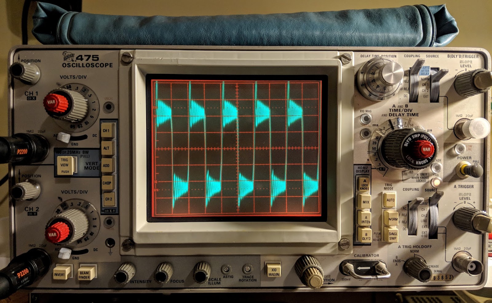
Watching a capacitor charge 250 times a second
The lines are a bit wide because the signal source was noisy

Tek 475 Specs

The Tektronix 475 is a portable (30 lbs), dual-trace oscilloscope with dual time-bases similar to the 465, but with 200 MHz bandwidth and a maximum vertical sensitivity of 2 mV/Div. It is all solid-state except for the CRT. It was introduced in November 1972.  

This scope cost $3,000 when it was new.  Now you can find them in good condition for less than $200.

  • Bandwidth --  200 MHz (475), AC cutoff 10 Hz, switchable BW limit 20 MHz
  • Rise time -- 1.75 ns (475)
  • Deflection -- 2 mV/Div to 5 V/Div, 1-2-5
  • Cascaded mode -- 400 μV/Div, 50 MHz with CH1 input connected to CH2 VERT SIG OUT
  • Time base -- 10 ns/Div to 500 ms/Div, 1-2-5, and ×10 magnifier
  • Input impedance -- 1 MΩ // 20 pF
  • Triggering -- 0.3 Div (int) or 50 mV (ext) to 40 MHz, increasing to 1.5 Div/250 mV at 200 MHz; AC coupling >60 Hz; LF REJ >50 kHz, HF REJ <50 khz="" li="">
  • X bandwidth -- 3 MHz
  • Z axis input -- 5 Vp-p, 50 MHz
  • Calibrator -- 1 kHz, 30 mA / 300 mV square wave
  • Outputs -- CH2 Vert Signal Out, 20 mV/Div into 1 MΩ or 10 mV/Div into 50 Ω; A and B +GATE OUT, +5 V; Probe power jack
  • CRT -- 8 × 10 cm², P31 phosphor (P11 opt.)
  • Power -- 110, 115, 120, 220, 230 or 240 VAC ±10%, 48-440 Hz, max. 100 W

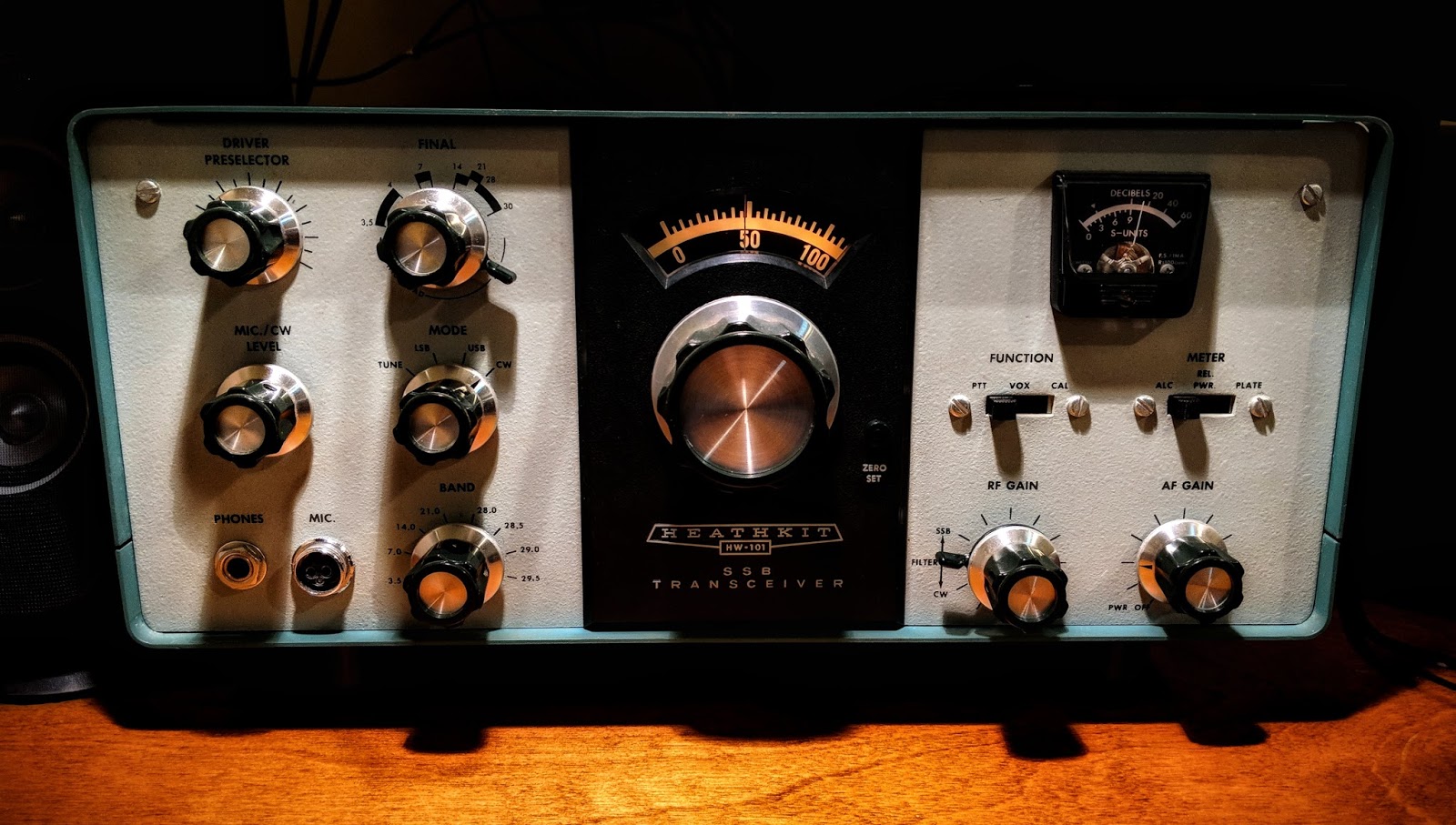
Real knobs and switches

One advantage of an analog scope is that there is a labeled switch or knob for every function. No need to dig through menus to figure out how to do something.  To me this is the a true advantage to finding a well calibrated, analog scope.


An oscilloscope needs a function generator

An scope let's you visualize AC within a circuit, but when you testing  something you often need to inject AC into that circuit.  That's the role played by a function generator.  Function generators allow you to choose a frequency and a wave type (sine, triangle, square, etc.), or sweep across frequencies.

In general, the higher the frequency they support the more they cost.

If you have a mobile device you can get one that uses your headphone jack as output up to 22 kHz for free...


For a free app it is very nice.  It outputs sine waves very well, triangle waves are a bit soft pointed and square waves are for entertainment purposes only.  But it is free so I won't complain.  In the image below you can see the oscillations as it tries to generate a square wave but the audio amplifier of the mobile device just doesn't have that kind of control.

Frequency Generator App set to 1 kHz

Square Wave?

Square waves are not

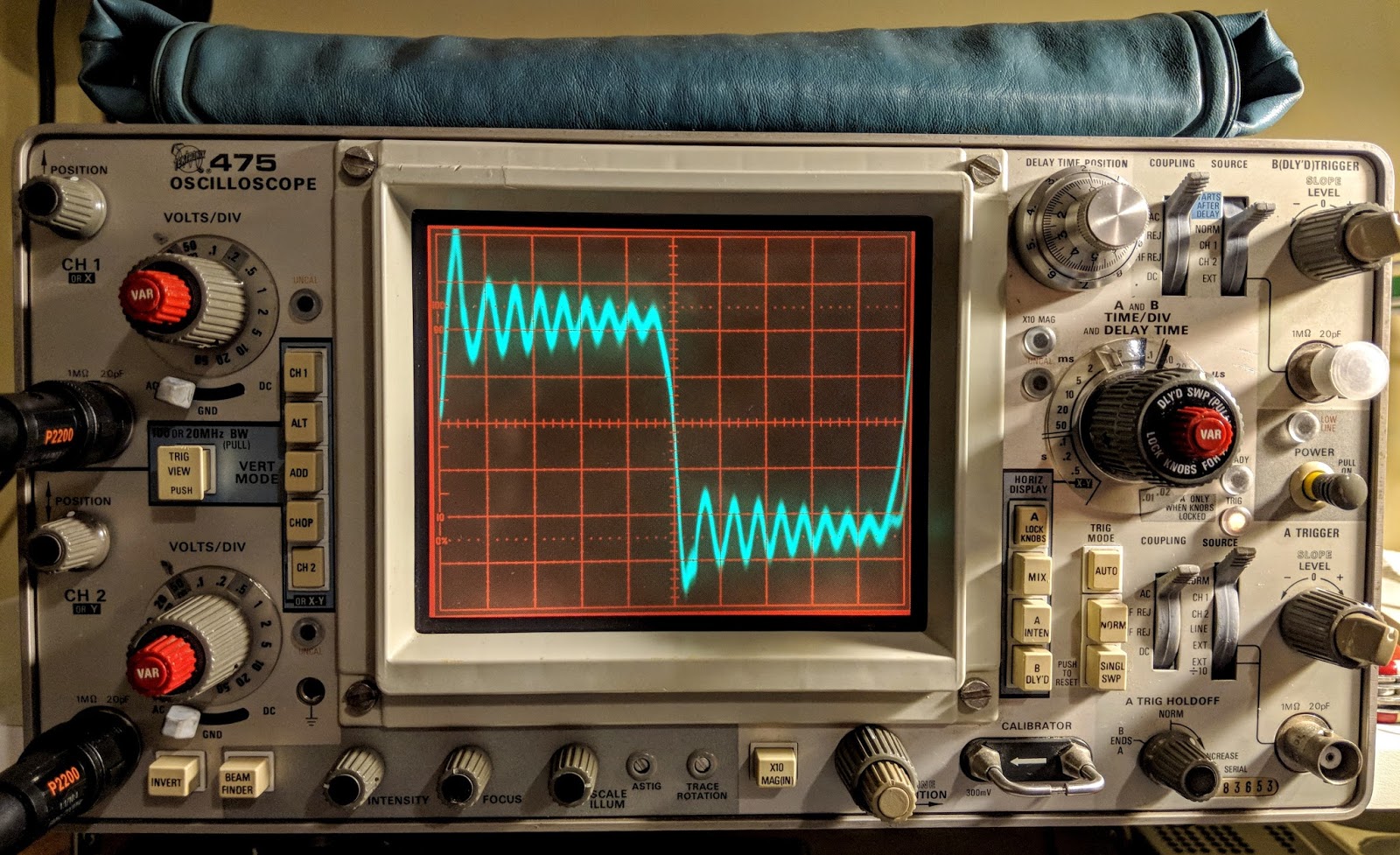
Reduce the time base to zoom in

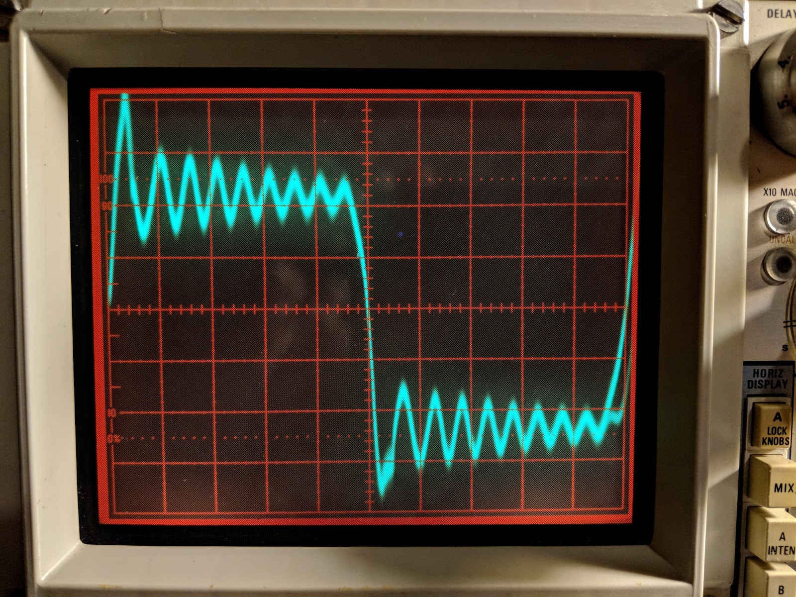
Yea, square wave.... not so much

The square wave is bad but sine and triangle waves look good until the frequency get's near the top of the range or the amplitude is raised too high.

Sine Waves look good

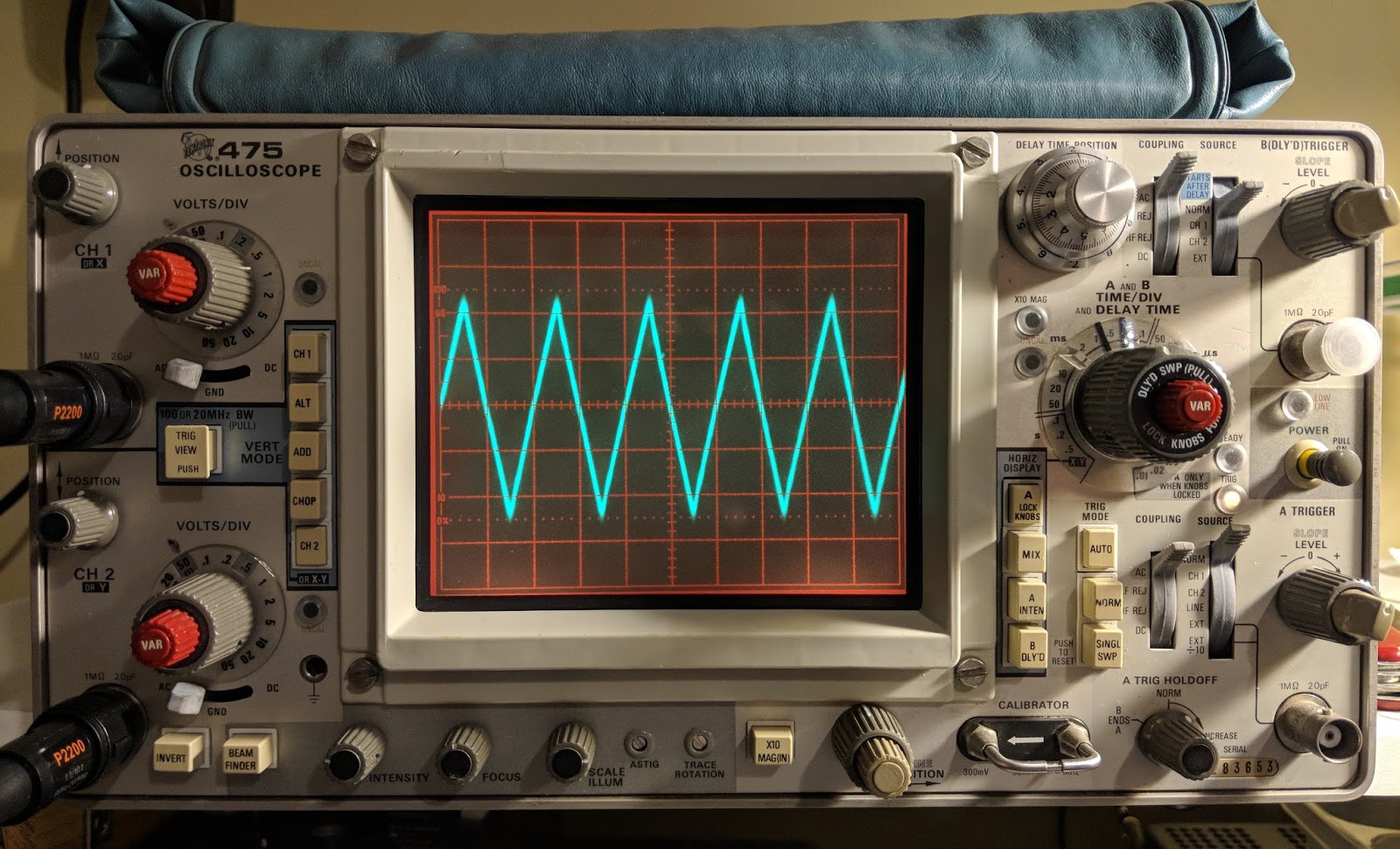
Triangle waves are on as well until you go up in frequency


The free app is inadequate for bench testing

While I appreciate that this would be a useful, portable signal generator for testing audio circuits, I'll be ordering a purpose-built function generator because generating clean square waves is an important test signal to be clean.  I also will need a generator that works above audio frequencies, hopefully up the the IF frequencies of the some of the equipment I'm testing.

Only the beginning

Having an oscilloscope is a new adventure for me.  I have another 1-watter kit ready to build that I've been holding off on because I wanted a scope for troubleshooting.  In the meantime I'm using the scope to watch transistors trigger and measure the timing circuits I'm building and learning how to control the scope.  The Tektronix 475 is a feature-rich analog scope.  If you plan to fix your own equipment or do some homebrew electronics work a scope can come in handy.


That's all for now

Sow lower your power and sample it with a scope

72/73
Richard AA4OO

Wednesday, February 28, 2018

Feeling gassy

Ionization is a beautiful thing


A reader asked me to video the pulsing of the OA2 voltage regulator tube in action. 

OA2 VR tube glowing beautifully in back corner


I turned the room lights down to capture the OA2 in its glowing gas glory and noticed a problem with the V15 6EA8 tube that creates the sidetone oscillation and Vox control. A patch inside was glowing a brilliant violet color when the CW switch was engaged. Glowing gas inside a gas filled tube is pretty but glowing gas inside a vacuum tube is a no-no.  I've noticed my sidetone volume (which is unadjustable) going a bit soft over the past week and now I understand why. The vacuum tube has developed a leak and has "air" inside.  That "air" is mostly nitrogen which ionizes with this brilliant violet color. 

Tbis 6EA8 should not be glowing violet

Lots of flatulent tubes


After I saw that I started looking and noticed I also have an 12AX7 beginning to go gassy as well so I ordered some new tubes from www.findatube.com

So let's keep the gases where they belong.

Solved a bit of a mystery tonight

I had a problem that I've just tracked down. Most boat anchor guys would probably already have known how to solve this but it a new discovery for me.

My audio was occasionally scratchy with a bit of popping.  Sometimes when working CW the other stations signal would jump around slightly in frequency, like 20Hz - 50Hz. 
I'd already re-seated most of the tubes, re-tightened screws, DeOxit'd switches, etc.  

Then I noticed that V1's tube shield was not bonded to the tube socket finger thingy (sorry don't know what it's called).  The other tube shields were soldered and I hadn't noticed that this tube shield was new and looking at the socket spring thing appears it had never been soldered.  After pulling that tube and its shield I scraped the paint from the shield where the socket spring presses onto it and cleaned the socket spring as well.  Apparently those tubes leak RF and the tube shields catch the stray signals and send them to ground.  Without proper bonding the tube is spraying RF around.

That turned out the be the problem, now all is good. Received signals are rock steady and the audio is very clean.  

Tube shield needed to be grounded to the socket spring


This problem had been periodic and was driving me a little nuts.  I'd read that grounding the tube shields was important but somehow I'd missed that this shield was not properly bonded to the finger thingy.

On the positive side, I am growing a tube collection by purchasing replacements that are not needed :)


That's all for now

So lower your atmospheric pressure and raise your B+ voltage

Richard AA4OO

Saturday, February 24, 2018

Voltage regulation, tube style

High voltage indeed

The Meter on my Heathkit HW 101 stopped displaying ALC (dropped down to the negative stop).  So, I opened up the old rig to have a look. I found that the B+ voltage was reading 33 volts higher at one of the test points than it should. Ultimately that voltage didn't turn out to be the problem with the alc meter instead the meter switch had become dirty and needed to be cleaned. But in the process it got me to studying the way voltage is regulated in the Heathkit and I learned a bit about voltage regulation tubes like the OA2 used by Heathkit.

OA2 tube
OA2 in action at the right rear of the Audio board, notice the glowing gas inside

More Glow...

Look at the pretty violet glowing gas in the OA2

The OA 2 is actually not a vacuum tube it contains a gas that ionizes and in the process of ionization acts as a voltage regulator.  In a vacuum tube, if you see glowing gas inside the tube that means it's leaking and has become "gassy", that's a bad thing.  In the case of a gas filled tube like an OA2 you expect to see glowing gas and if you do not, then there's a problem.

In this case The OA2 regulates voltage to 150 volts and current is limited by the two high-wattage resistors connected in circuit to that tube (seen beside the OA2 in the photo above). Those resistors are dissipating a lot of heat.  I measured over 300F degrees with my IR temperature gauge (ouch).

Tube Testing without a tube tester?


I emailed one of the members of my local club, Joe WA4GIR to ask about tube testing and he sent me the following,  which he gave me permission to post:

The lack of a tube tester is not a limitation.  You can tell a lot about a tube test by looking at the voltages in the circuit.  If the filament goes out, the tube is dark and does not conduct.  That one is pretty obvious.  If the tube cathode loses it's ability to emit electrons, the voltages dropped across the cathode resistor and any resistors in the plate or screen grid circuits will change (the voltage drops across those resistances will drop).  A good tube tester will measure the ability of the tube to vary the plate current for changes in grid voltage, and you can see this with a scope by looking at the AC voltages on those elements, at least for the audio circuitry.  Probably not so much for the RF circuits as you are affecting the circuit when you probe it.  The best way to check for a suspect tube is to replace it with another.  I have 0A2's new in the box.  I may have the other tubes pulled from radios but it takes longer to look through those as sometimes the numbers are hard to read.  Hint. to bring out a faded number, rub it on the hair on the back of your neck-- better if it's oily.

A lot of resistors in old tube-type radios were 20% tolerance so don't expect the voltages to be that precise.  Tube rigs had much more variability than modern solid state circuits.  For the unregulated voltages, the precise voltage will depend component tolerances, tube health, and line voltage.  The line voltage here is about 125 when where I lived in Raleigh it was around 110.  You can do the percentages but that alone will account for some of the variation you might see.  I don't think that any of your tubes were damaged by overvoltage.  If they are drawing too much current, they will get hot, and in severe cases, the plates will glow red.  That's a concern.  Much less than that, the life might be reduced but I don't think you will see any short term effect.  When I've run tubes too hot, you might see signs of the tube going gassy, which is indicated by a blue low in the space inside the tube that is supposed to be a vacuum.

If you want to see the plates of a tube glow red, operate the final mistuned so it is drawing too much current.  They will glow red, haha.

The voltages out of the 0A2 are different -- they should be held pretty closely to 150V. I don't know the exact tolerance.  It might be a few percent.  So in your radio, 150V supply and any that are derived from it are the only ones that would have a  tighter tolerance.  The 0A2 has an operating current range of 5 to 30ma, and an operating voltage of 150V.  The supply voltage should be at least 185V to get the tube to "fire" but once "on", the voltage feeding will drop to the 150V level and be regulated there by the action of the tube which causes the voltage drop across to change (like zener diode regulators).  The regulation comes from the fact that a very small increase in the voltage across the tube results in a significant increase in the current so the resistor values are chosen so that the current through the tube remain in the 5 to 30ma range as the input voltage and the current draw of the regulated circuits varies for whatever reason.  Remember the current draw when you first turn on the rig will be low because the tubes don't conduct until the cathode gets heated so the designer must account for that in the selection of the input resistors to that circuit.

More to learn about hollow state


As a young-ish ham I certainly have a lot to learn about old tube radios but I'm enjoying the journey. Just the thought of transistors operating by thermionic emission, tossing their electrons across empty space, being attracted to a plate with more positive voltage is fascinating to contemplate.


That's all for now

So lower your power... or at least regulate it with a OA2... and raise your expectations

73
Richard, AA4OO

Saturday, February 17, 2018

Self-service audio station report

Get a remote signal report via WebSDR

I've been making modifications / upgrades to my old Heathkit HW-101.

I've had a good number of CW QSOs and a couple of phone contacts with it so far and received good reports.   One concern I had, regarded losing the first DIT of a letter on initial relay closure.  There is an upgrade article for the HW-101 with a section describing a fix for losing the first DIT of a letter on the initial close of the relay.  The modification involve replacing a resistor with a lower value that triggers the VOX.  It's a resistor change from 470k to 1k which seems kind of extreme to me.

According to the article you will hear the initial DIT in the sidetone but above 20wpm that DIT is not transmitted due to a delay of the relay closure because it's driven by a VOX circuit.

This test is difficult to describe to a remote CW operator.

I recalled that webSDR stations usually offer a remote recording facility.  I found a webSDR station that was within propagation on 40m today and sent my CQ with my call while recording from that remote station.  My call, of course, begins with  the letter A, which begins with a DIT.  I paused for the VOX delay to timeout between sending my call-sign, thus causing AA4OO to be sent with the relay closing at the beginning each time.  I started the recording before my call and stopped when I was finished and downloaded it.

remote webSDR station recorder

I confirmed, that although the initial DIT was shortened a bit above 20wpm, it was still being heard and didn't affect copy of words that began with a DIT on relay closure.  So I've decided to not do that modification at this time.  I previously used DEOXIT on the both sets of relay contacts in the HW-101, because there seemed to be some corrosion present that was affecting receive at times, and that has cleaned up the performance of the relay considerably.

So if you're wondering how to get a remote signal report when no one is answering your call the facilities of a remote webSDR station may help.

NOTE: The HW-101 doesn't have a precise VFO readout, even after calibrating it with the built-in crystal calibrator.  I use the reverse beacon network to spot me and take the frequency reported by remote beacon to enter into the frequency of the webSDR station to find my signal.

This works for getting a SSB report as well

This is also useful for determining how your SSB signal sounds.  So if you verify your audio from a remote station, try using a remote webSDR station recording capability for checking your rig.

One way transmissions are prohibited aren't they?

You may be thinking that using webSDR to check your station might be considered a one-way transmission or fall under the prohibition to broadcast by amateur stations.  But Section 97.111(b) provides for one-way communications. In summary, auxiliary, beacon, space and stations in distress are specifically authorized to make certain one-way transmissions. Additionally, an amateur station may transmit the following types of one-way communications:  Brief transmissions necessary to make adjustments to the station; ...

So just keep your transmissions brief and only use them to make adjustments.  I send them as a CQ and follow-up if I receive an answer to my call.


That's all for now

So lower your power and raise your expectations

72/73
Richard, AA4OO

Tuesday, February 13, 2018

The dark side

Oh my, what have I done

Don't take away my QRP CW card. 


I picked up an old, high impedance Heathkit microphone having the appropriate 2-pin connector.  One pin is the mic line and the other is for the PTT switch. The shield is common.

I set the mic level to indicate some movement on the ALC and peaks were occurring around 100w.  QRP SSB will be tough to achieve.  

I worked a few stations on 80m and they delivered great reports and offered their own stories of Heathkit radios. 

The old rig is certainly a conversation starter.


That's all for now

So... well, my QRP saying doesn't go with this post, so...  warm your tubes and smell the cooking resistors 

73

Richard AA4OO

Monday, February 12, 2018

Totally Tubular - images

The inside of a Heathkit HW-101 is too interesting not to photograph

List of tubes and their function used in the HW-101

OA2 Regulator (150 V).
6HS6 RF amplifier.
6HS6 1st receiver mixer.
6AU6 Isolation amplifier.
6AU6 1st IF amplifier.
6AU6 2nd IF amplifier.
6BN8 Product detector and AVC.
6AU6 VFO Amplifier.
6CB6 2nd transmitter  mixer.
6CL6 Driver.
6EA8 Speech Amplifier  and cathode follower.
6EA8 1st transmitter  mixer.
6EA8 2nd receiver mixer and relay amplifier.
6EA8 CW side-tone oscillator and amplifier.
6GW8 Audio amplifier and audio output.
12AT7 Heterodyne oscillator and cathode follower.
12AT7 VOX amplifier and calibrator oscillator.
12AU7 Sideband oscillator.
6146 Final amplifiers (2).

The glowing filaments and grids of tubes are a sight not often seen in today's transistorized world of amateur radio.  I hope you enjoy the images...


Video with CW QSO

Brief video ending with WES exchange CW QSO.  Listen to the old girl in action...


Update:

Great resource for information on tubes and old radio design...


That's all for now

Saturday, February 10, 2018

The Heathkit HW-101 lives again

Ah, the sweet smell of hot tubes and resistors

Heathkit HW-101 after it's first QSO under new ownership

I completed my rebuild of my Heathkit HP-23B power supply this morning.  There was a bit of frustration on my part as I followed the instructions because they only have photos of a HP-23 which has adjustable bias and no LV switch.  

It left me scratching my head a couple times, and I had to locate a schematic of a HP-23B to complete the work.

Heathkit HP-23B Schematic

I really need to learn more about electronics

In the midst of the rebuild I thought I had a problem with the transformer.  Both low voltage winding taps (275v and 350v) showed very low resistance (about 5 Ohms) to chassis ground, which led me to believe there was a short in the transformer.  

I called my mentor in all things Ham radio, Paul AA4XX, and described the issue.  He walked me through the schematic and had me unsolder a couple points to confirm his guess that all was well.  That double tap, low voltage winding presents very low resistance to ground but it is not a short in the world of AC.  I continue struggling to wrap my head around the differences in AC and DC, but I'm slowly learning and fortunately haven't caught anything on fire yet.

Out with the old, in with the new

Old components

Testing High Voltage

My Multi-meter can only measure up to 600v, so in order to measure the 800v output I used two 3 watt 100 kOhm resistors in series as a voltage divider.  When in use, the MM will read half the voltage.

Voltage divider for measuring the high-voltage output
With the voltage divider the HV power measured 401v which works out to 802v undivided

Completed upgrade


The kit places all the components in the base and the holes that the old big filter capacitors used to be in are now just ventilation.  I need to put a wire shield over those holes because high voltages are present just below, as well as some really hot resistors.  With the top cover back on it, there shouldn't be a problem but the wire mesh shield is still recommended, especially if it's to be used inside a Heathkit speaker, where the top cover is not used.

With the PCB board, all the components are out of sight in the base except the big resistors

Replaced the HW-101 antenna connector with a BNC

Original antenna connector was a RCA with questionable integrity.

Original RCA antenna jack (viewed from inside chassis)

Replaced with BNC jack which fits without enlarging the original hole.

New antenna jack

The old radio now has power 

I replaced the old paper 350v 20uF electrolytic capacitors in the HW-101 and then connected the power cable and switched it on via the switch in the HW-101.  I didn't hear any audio at first and thought something was wrong.  Silly me, those tubes need a bit to warm up.  After a minute I was hearing audio and used the built-in crystal calibrator to check the VFO dial.  It was pretty close to spot on.

I ran through some initial checks according to the Heathkit manual.  Receive worked well.  I listened to some SSB and then dropped down to the 40m CW portion of the band and listened to CW.  I waited about 30 minutes for the tubes to warm up.  I didn't hear any drift on CW stations I was monitoring.

I found an open frequency, checked the plate current and then tuned up, outputting only about 10 watts because I don't know what state of alignment the finals are in yet.  This is the first time I've tuned a tube rig and that was interesting.  You have to peak the preselector in receive mode first, then when in tune mode, quickly work back through the preselector, final tune and load levers to peak the RF output.  It reads more complicated than it actually is.  My OCFD antenna has about a 1.7:1 SWR on 40m so it didn't need much tweaking from the initial settings.

I tuned around and answered N4PGJ, Ron in NY, and had a brief WES exchange.  The relay control time set by VOX delay needs to be bumped up a bit as it was dropping between every word break, but other than that it worked like a charm.

I'll make a video soon, but initial impressions are positive.  The audio quality was astoundingly good, and the CW filter really did a much better job than I expected.  It has a very pleasant sine-wave sidetone rather than the raspy square wave sidetone of my Ten-Tec Century/21.  I really think I'm going to enjoy using this old rig.

UPDATE

I got the rig buttoned up and on the desk.  Here's a video...


Oldie but goodie


That's all for now

So lower your power and warm up those tubes.

72/73
Richard AA4OO