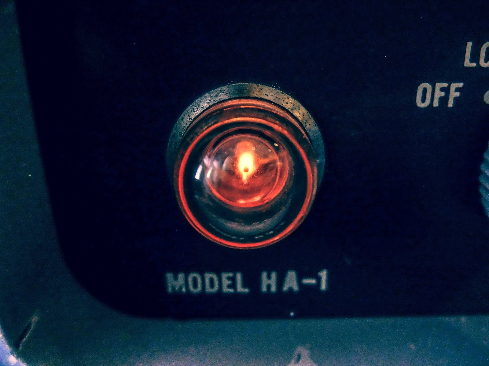
🗲 Heathkit VTM model IM-11 🗲
I recently got a taste for restoring and using vintage vacuum tube radio equipment. Using equipment that requires 800+ volts for making QRP transmissions is counter-intuitive to the spirit of QRP ham radio, but it's part of my journey as a ham, so I'm writing about it. Bear with me. Once I receive a near fatal shock I'm sure I'll move back to 12v powered equipment again.
Until then...
One of the first issues I ran into while testing the
power supplies I restored for my vintage gear was how to measure voltages beyond the range of my digital multi-meter. Most consumer grade digital multi-meters (DMMs) can only measure up to 500 volts then display an error, or stop working altogether. Previously, I was able to measure voltages over 500V by making a voltage divider out of two 100k 1w resistors and taking my measurement from the middle of the two resistors, but it was precarious in use and added even more danger when working with this old equipment.
I'd looked at getting a DMM capable of measuring high voltage, but the recommended ones, like a Tenma 72-1055 Benchtop Digital Multimeter, start around $100. Used Fluke meters are even pricier. I'm sure buying a more professional DMM would be a wise investment. As I've evidenced many times; wisdom is omitted from my DNA.
So what did hams of yesteryear use?
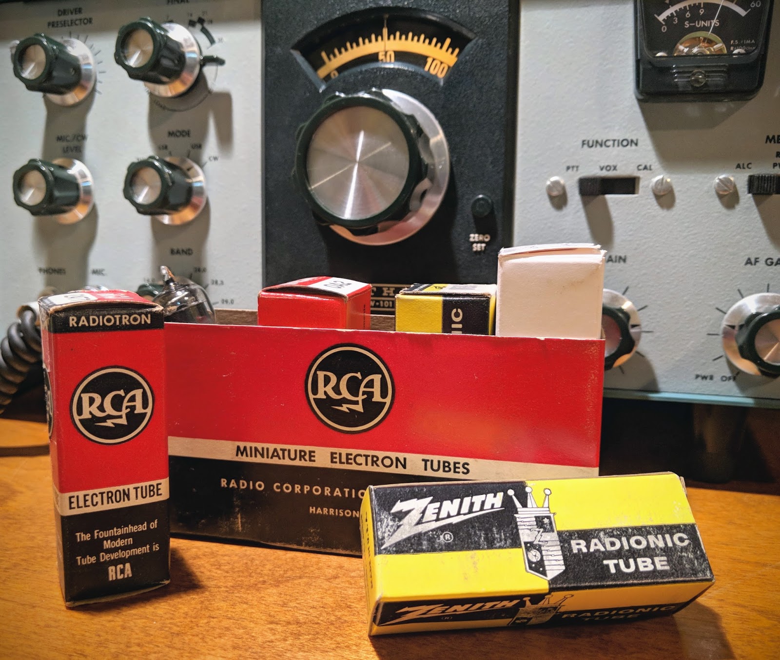
Behold... Vacuum Tube Volt Meter
Vacuum Tube Volt Meter
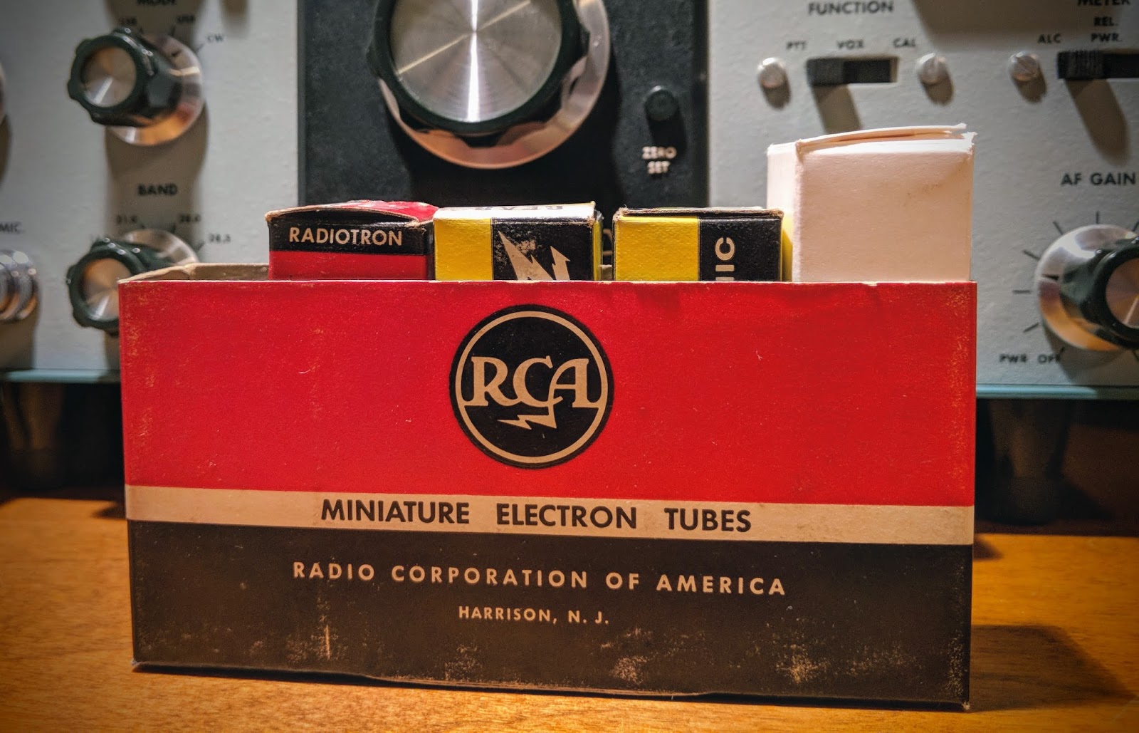
This Heathkit VTVM model IM-11 was available at my local Hamfest (Rarsfest) for
5 dollars.
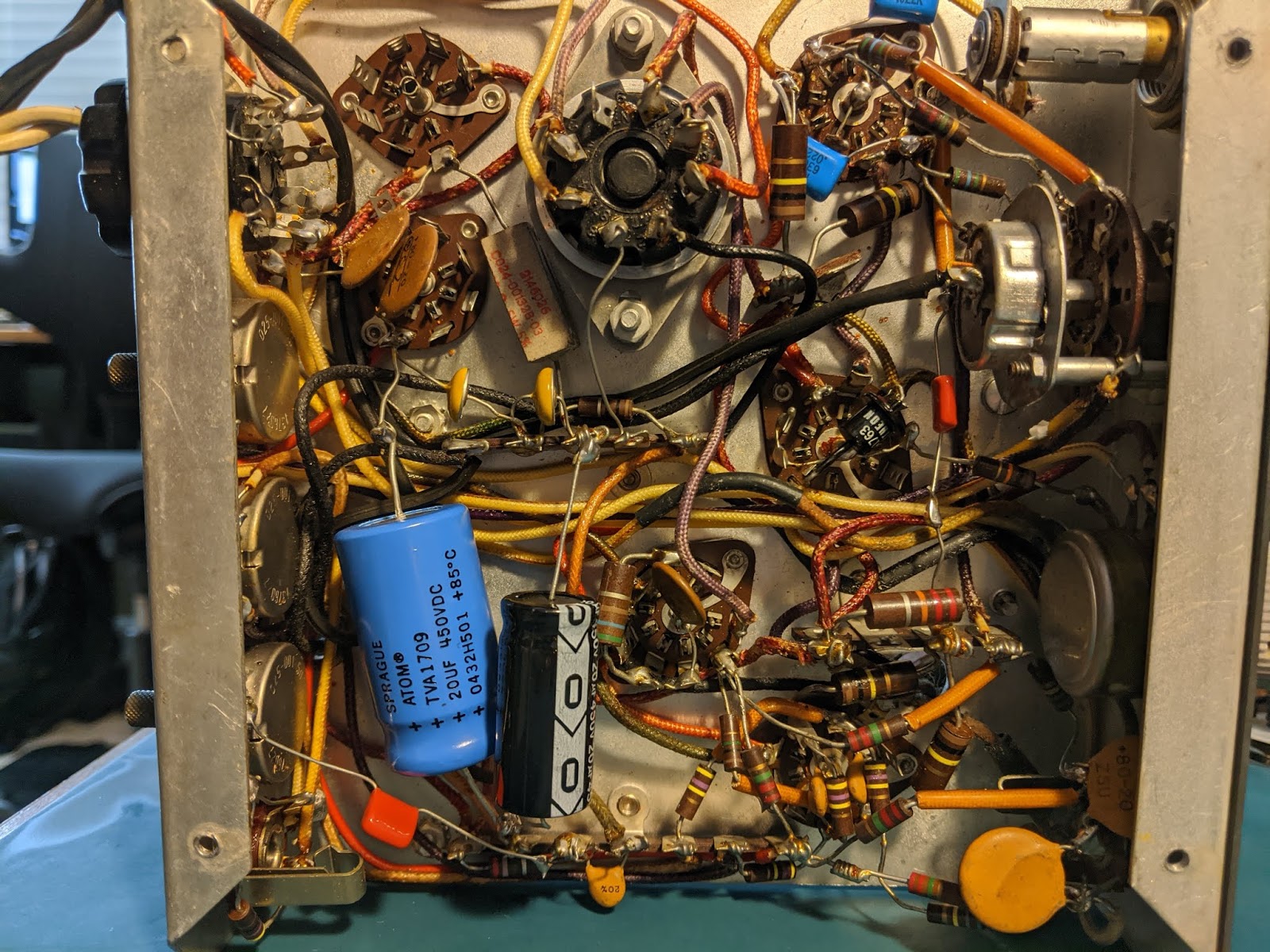
Debugging
Five dollars is not a princely sum, but as with most things purchased from a hamfest, it required some attention.
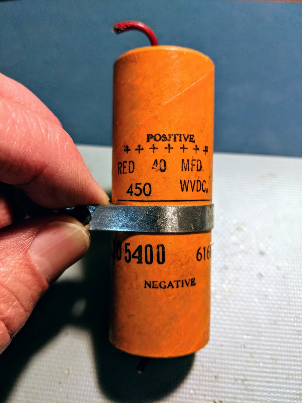
The 55 year old 16uFd@150V paper, electrolytic power filter capacitor was likely a ticking time bomb so I replaced it with a modern capacitor for safety concerns. The closest one I had was a 33uFd@160V radial electrolytic. I don't think double the capacitance will be a problem for a filter capacitor, it will just make the transformer work a little harder when it's first turned on. I calculated the initial charge time and it's 393ms vs 190ms for the original cap. I think the 10k resistor and transformer can handle the extra 200ms heavy load on power up.
A few wires inside the meter had come loose from some very sparse solder points and a one intermittent connection in the range switch was especially troublesome to track down.
The biggest mystery to solve was oversensitive resistance readings in the Ohms mode. I replaced the C-cell battery in the battery cup and while I had it out I glanced at the + connection for the battery in the cup. I appeared to have oxidized at some point in the past and was discolored. I scraped it off until I saw shiny bits and thought all was good. I spent more time tracing the circuit and thought I had a problem with the switch itself or the 9x resistors in the range circuit, as suggested in the troubleshooting section of the manual. The problem turned out to be that oxidized bolt head that formed the positive battery connection in the battery cup. Scraping it had not provided electrical contact. In fact, when I removed the bolt (after having to disassemble the circuit board from the meter for the 2nd time), I filed down the head of the bolt and could find no conductive metal left. I'm guessing that a former leaky battery had converted the entire head of the bolt to a very hard, yet non-conductive material. I've never seen anything like it before and it proved to be a useful lesson.
I had to find a replacement bolt and that lead to working on my lawn mower and then mowing the yard... not sure how that progression occurred... Eventually I got the new bolt in the cup, the circuit board re-installed. Ohms tested accurately, put it all back together and noticed the #50 pilot lamp had stopped working (sigh). I removed the innards from the case one more time and got the pilot bulb settled (I think it's required to balance the filament circuit). While I had it apart for the umpteenth time, I decided to reconnect the 1/4" plug that a former owner had disconnected while keeping their original modification allowing 1 mega-ohm to be switched in for the outermost probe when DC functions are selected but switched out when AC or Ohm functions are chosen. I wanted to allow use of an original VTVM probe used in the 1/4" plug with its built-in 1 mega-ohm resistor.
Whew!
All-in-all, I probably spent 8 hours getting all the functions on my $5.00 meter to work, replacing old parts, undoing mods and aligning it for proper DC and AC readings. It's a good thing I don't count my time in the cost of these projects, otherwise I could have purchased a couple Fluke meters for the cost of my time.
What's the fun in buying something that works right the first time when you get it home, huh? Are we hams, capable of solving problems, or appliance users? Actually, it would have been nice if it worked without new parts and repairs, but I digress.
Back to the story
This meter can measure up to 1500 Volts 🗲
The main reason I purchased this is to measure the high voltage in my tube equipment power supplies and 1500 VDC should just about cover it.
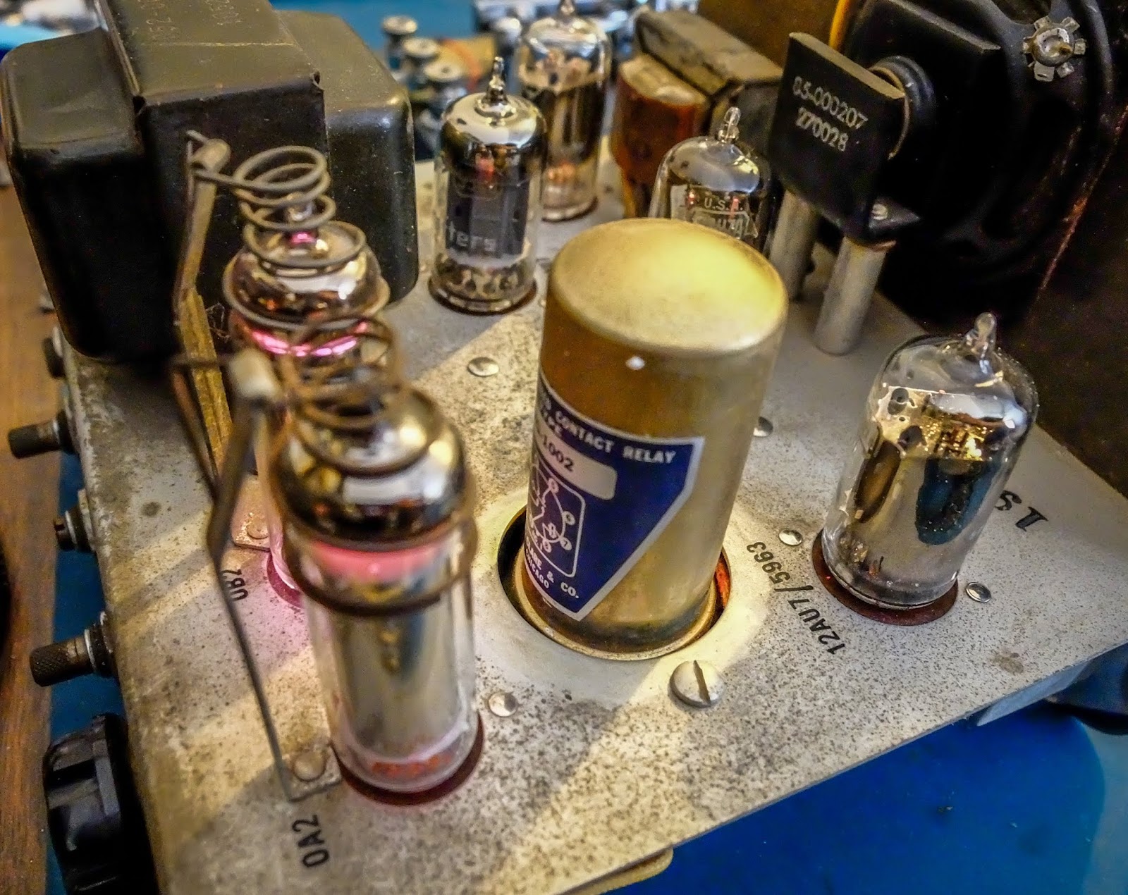
Although this meter uses a C-cell battery for measuring resistance, it runs off service mains to power the tubes which control the meter circuitry, so it must be plugged in to be used.
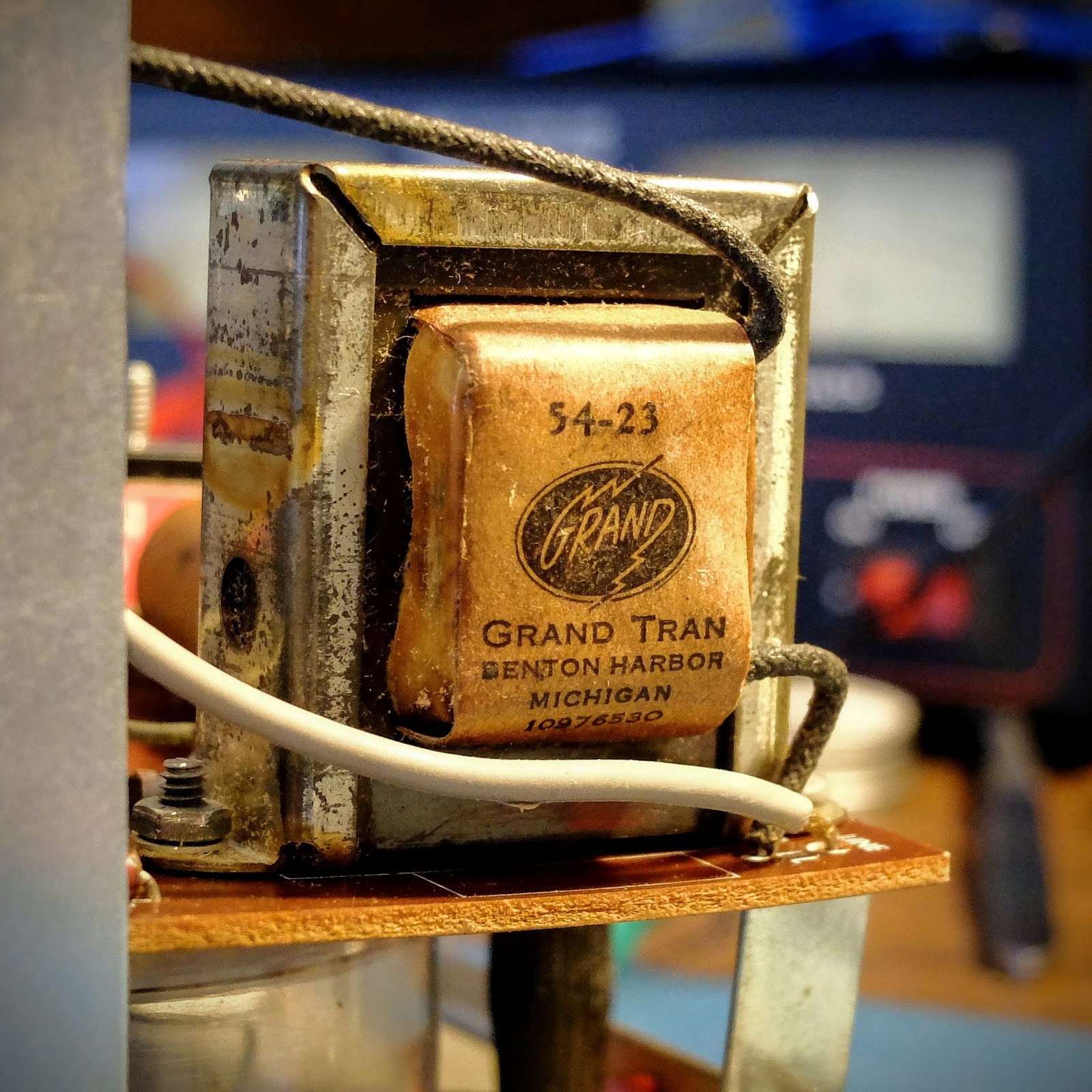
I love the look of its old "Gran Tran" power transformer inside the VTVM. They just don't make'em like they used to.
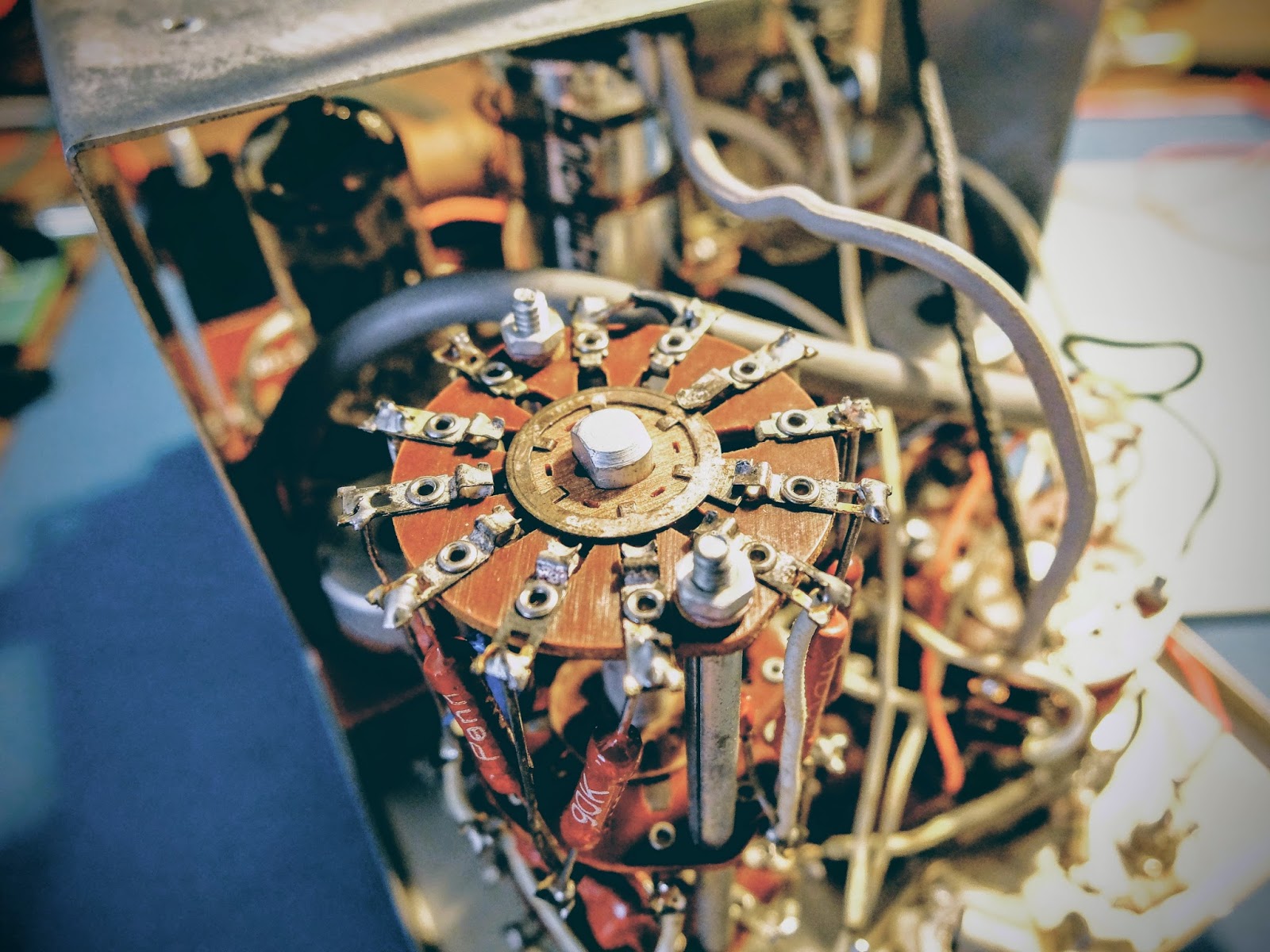
Wiring, lots of wiring
This model was made by Heathkit, from 1961 through 1968, and used typical point to point wiring of the time, making circuit tracing loads of fun.
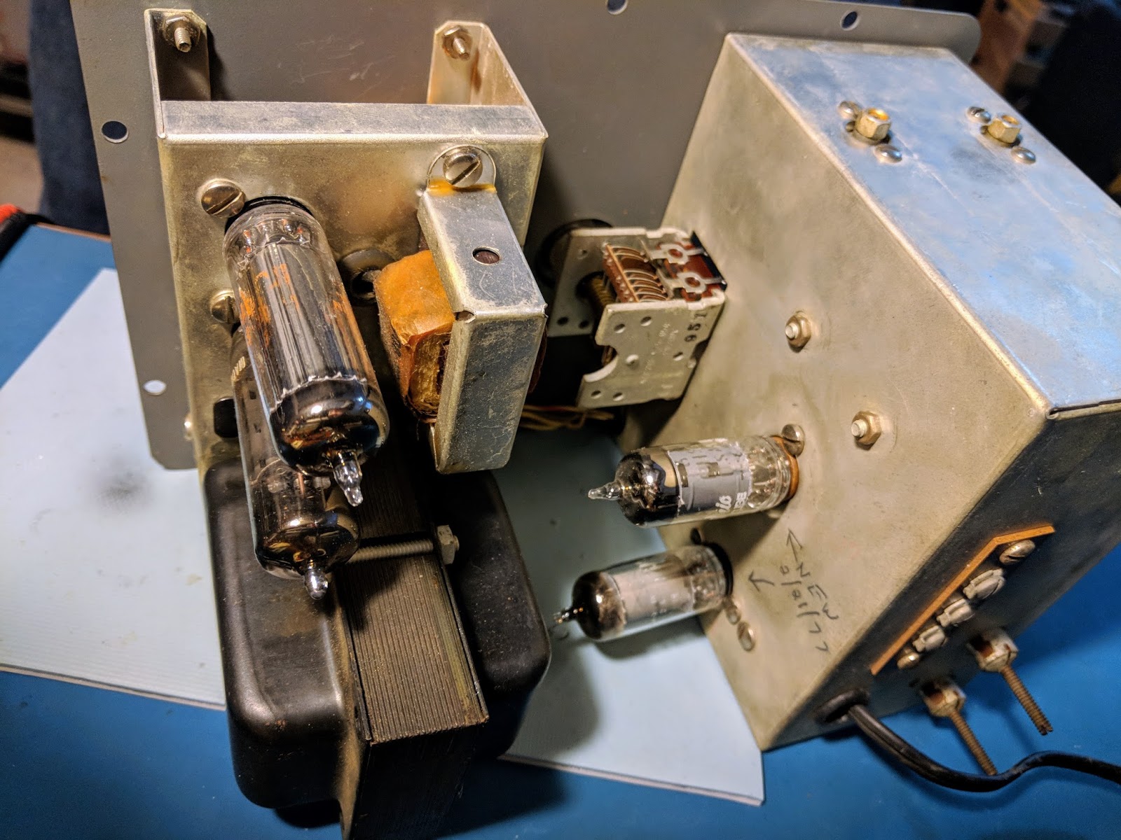
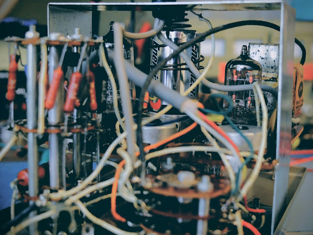 |
| Point to point wiring makes for interesting circuit tracing |
Shiver me timbers, it's got decks
Fun fact: When reading the schematic it will refer to "decks". A "deck" is a wafer section. When there are stacked sections as there are in the function and range controls the "front deck" is the one closest to the knob (front of the case) and the "rear deck" is the one furthest away, or in the case of working on it, the one closest to you. When there are more than two decks, as is the case with the range control, it will refer to the "second deck". As you'll likely guess by now, that is the second "deck" or wafer disc from the front of the instrument.
It also refers to "front half" and "rear half". The "half" is referring to a side of the deck, so in the case of "front half" it refers to the side of a particular deck facing the front of the instrument, while the "rear half" is the side of a deck facing back (or toward you).
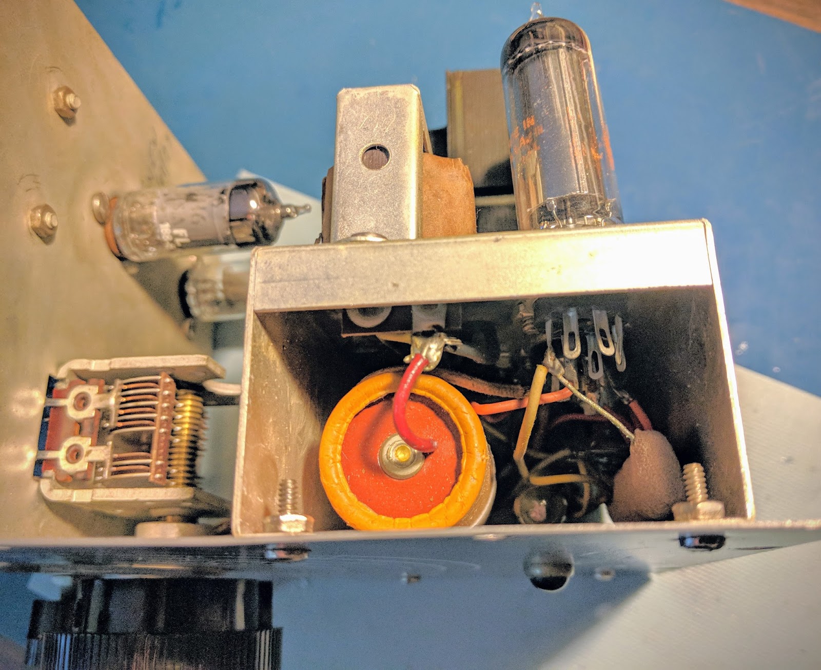
 |
| Clever voltage divider circuitry, what could possibly go wrong in this triple stack of wafer switches? |
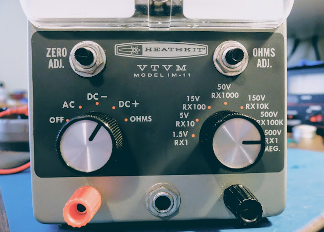
The left knob controls on/off and meter functions while the right knob controls the rather elegant voltage divider.
A knob for every function and a function for every knob. NOTE: do not plug your headphones into the 1/4" jack on the front unless you want to experiment with personal electro-shock therapy. Better, yet, don't plug your headphones in there.
 |
| Not clearly shown in this photo, voltage divisions up to 1500 volts supported |
"...Weighed in the scales and found wanting"
Ok, how many of you understand that completely unrelated biblical reference?
I haven't used a meter like this since I used to plan my VFR flights using an
E6B. My modern, digital multi-meter is fairly idiot proof in terms of reading the results. My DMM auto-ranges and displays the correct unit of measure along with the reading on its display. It works well for a dummy like me.
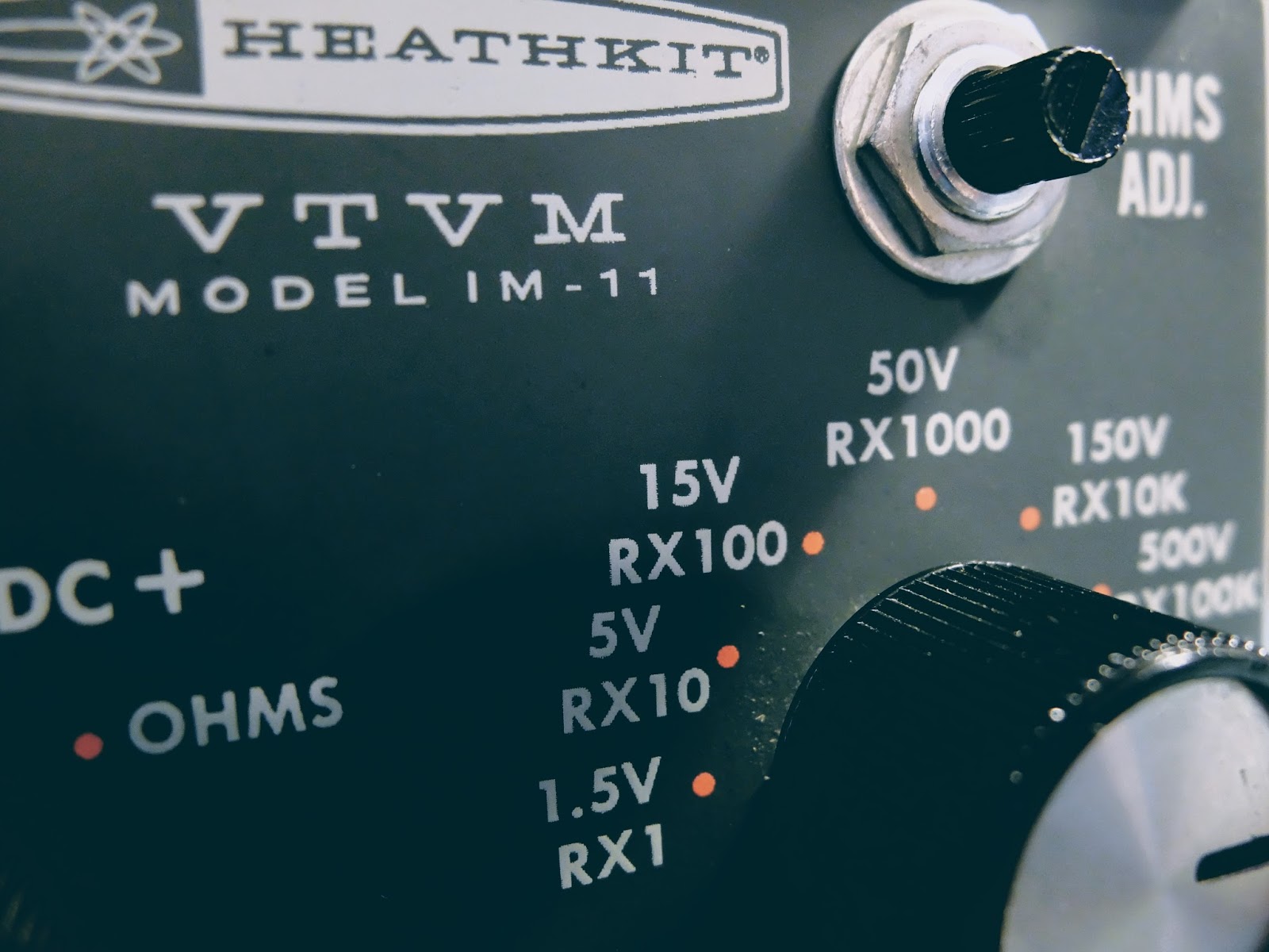
A VTVM on the other hand, has a number of scales that must be interpreted based on whether you are reading DC, AC or Ohms. Additionally, you have to pay attention to the range chosen.
 |
Choose a reading... any reading, just use the correct scale
Note: the needle isn't at zero in this photo because I had just plugged it in before taking the picture and the tubes hadn't warmed up. Ah, the joys of vacuum tube powered equipment |
The voltage markings for the range switch refer to the full scale reading. Resistance is the top scale, but let's ignore that because we're talking about measuring voltage... The second scale from the top is Voltage. Even though it appears to refer to DC for the numbers on the top and AC for the numbers on the bottom of that second scale that's not what's going on. The second scale is for both DC and AC. The numbers on the top are when you are using a range that is a multiple of 15, such as 0-1.5V 0-15V 0-150V 0-1500V. The numbers on the bottom of that scale are for the ranges using a multiple of 5, such as 0-5V 0-50V 0-500V. Clever eh?
You have to do a bit of math. For example, if you if you're using the 1.5V range take your reading and move the decimal place one to the left. So, a reading of 8 would represent 0.8V in the 1.5V range, while it would actually represent 8V in the 0-15V range and 80V in the 0-150V range, etc. See, hams were smarter in the 1960s.
Always start with a range larger than what you expect the voltage to be and reduce the range for a more accurate reading if it occurs in the lower 3rd of the range. The voltage divider set by the range knob is protecting the circuits so if you have it in too low a range and apply high voltage, bad things will likely occur.
Old school needle gauge. There's a lot going on behind that needle. It operates very smoothly.
 |
| Sporting some temporary probe hookups |
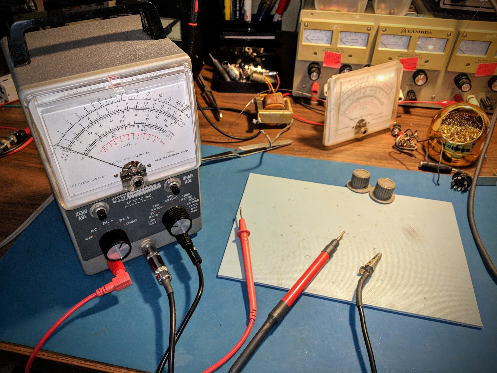
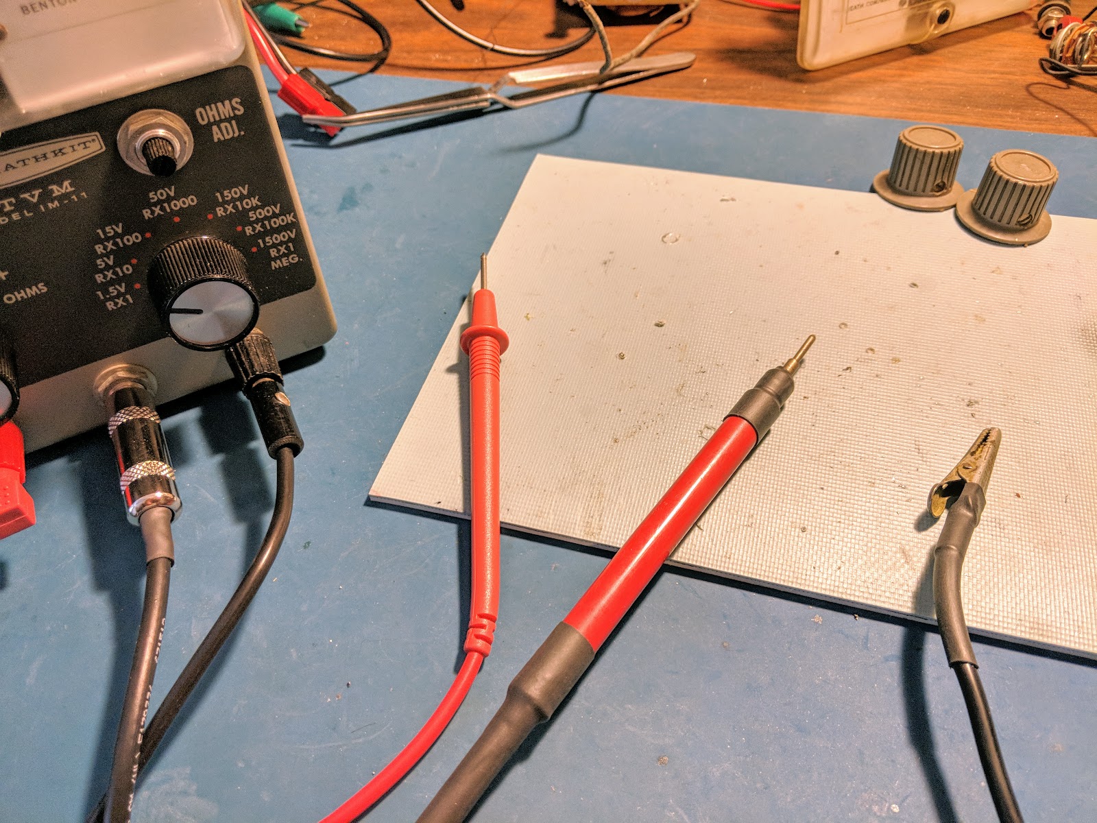
Making probes
This meter did not come with probes. I bought another older VTVM pretty cheap, for parts from a famous auction site because it was advertised as having a full compliment of probes, but alas, they were not usable. Even the 1/4" plug from those probes was a bust. However they did come with rebuildable probe "ends"
I used a RG-58 cable as the high voltage DC wire using only the center conductor and grounding the shield even though it is not used as the ground return. I also placed a 1/4 watt 1 mega-ohm resistor at the tip of the probe to limit any current through the probe cable. That cable terminates in the 1/4" plug and is wired such that it is out of the circuit in the Ohms position. I secured the cable into the probe body with some glue and used two layers of shrink wrap as a strain relief. I also put some shrink wrap near the probe tip as a bit of extra insurance.
I used a spare DMM cable for the outer positive banana plug feed used by the AC and OHMS circuit and made a heavily insulated cable with an alligator clip for the ground probe that goes to the other banana plug.
The outer probes are used for measuring resistance, AC and low volage DC. The center probe is used only for high voltage DC positive. Both positive probes would not be connected at the same time (as they are in the image below), and would present a shock risk if they were both connected when measuring voltage.
Summary
If you need a way to measure high voltage or are looking for a really eccentric meter to make common measurements harder than they should be get one of these VTVMs. They seem to be commonly available at hamfests and on famous auction sites for under $10.
Dazzle your friends next time they ask you to measure something for them, by whipping this not-so-little-puppy out of your back pocket and powering it up. As you're making your measurements quietly repeat "Mmmm, yes. Mmmm yes, I see now". They'll have no idea what you're referring to and be quite impressed.
That's all for now...
So lower your power and measure it with the low-range on your snazzy Vacuum Tube Volt Meter
72/73
Richard AA4OO


