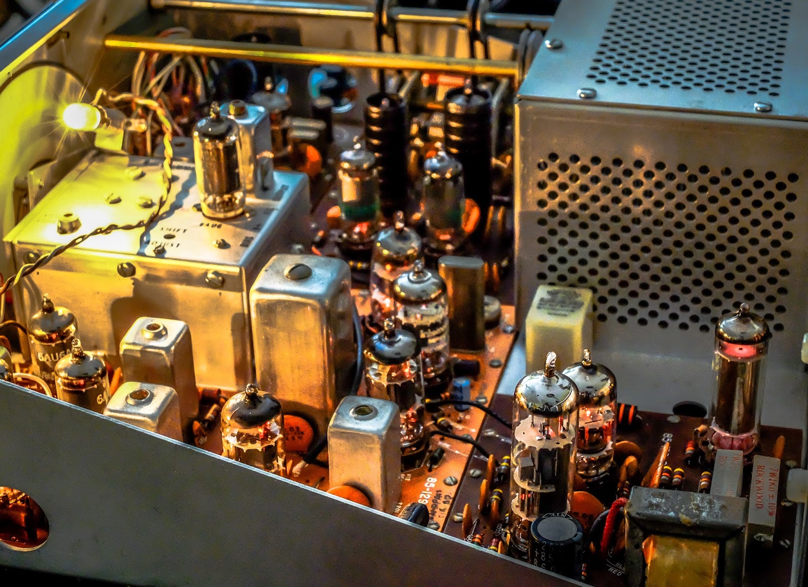
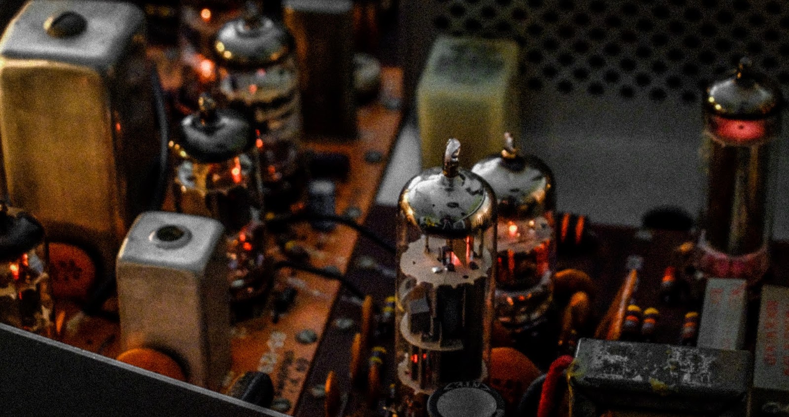
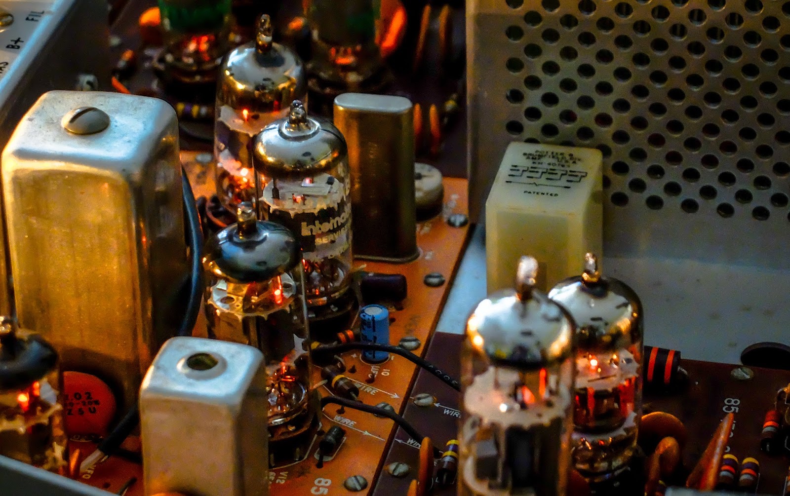
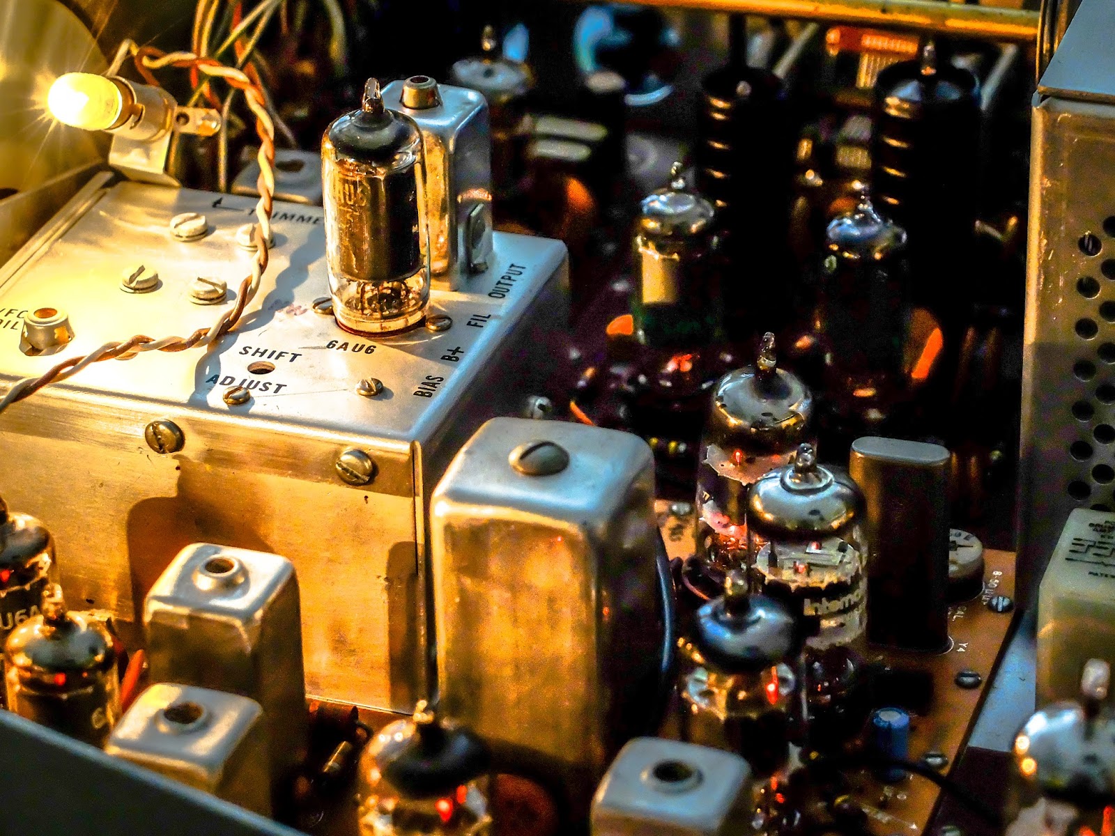
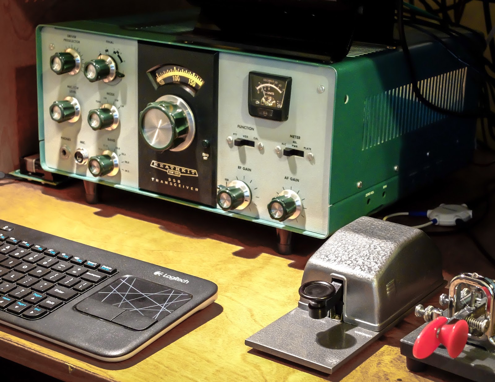
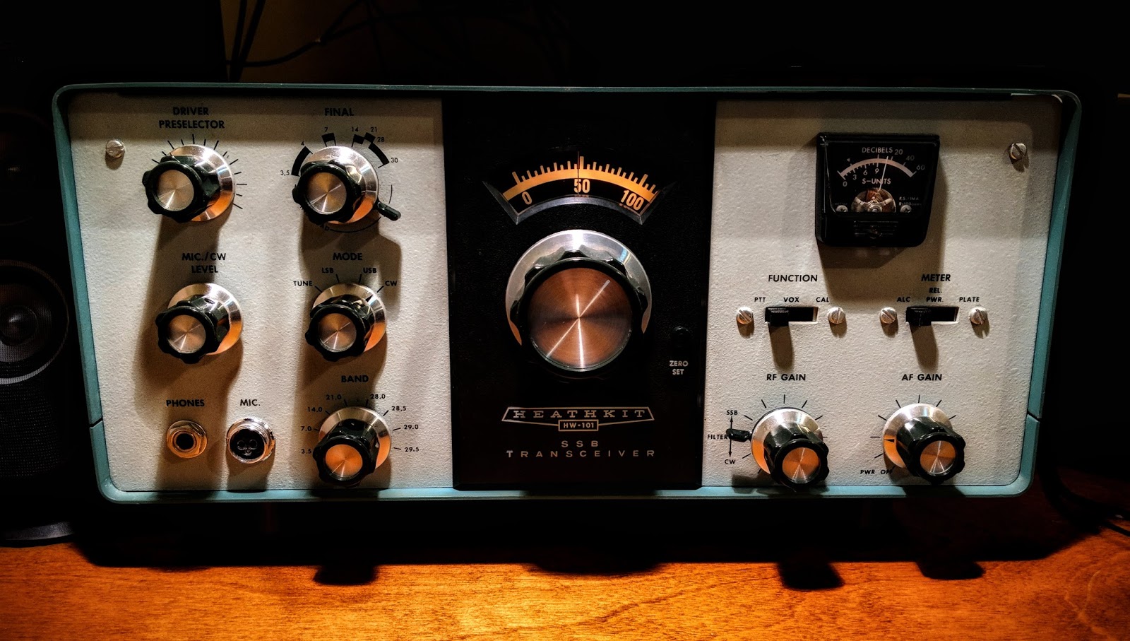
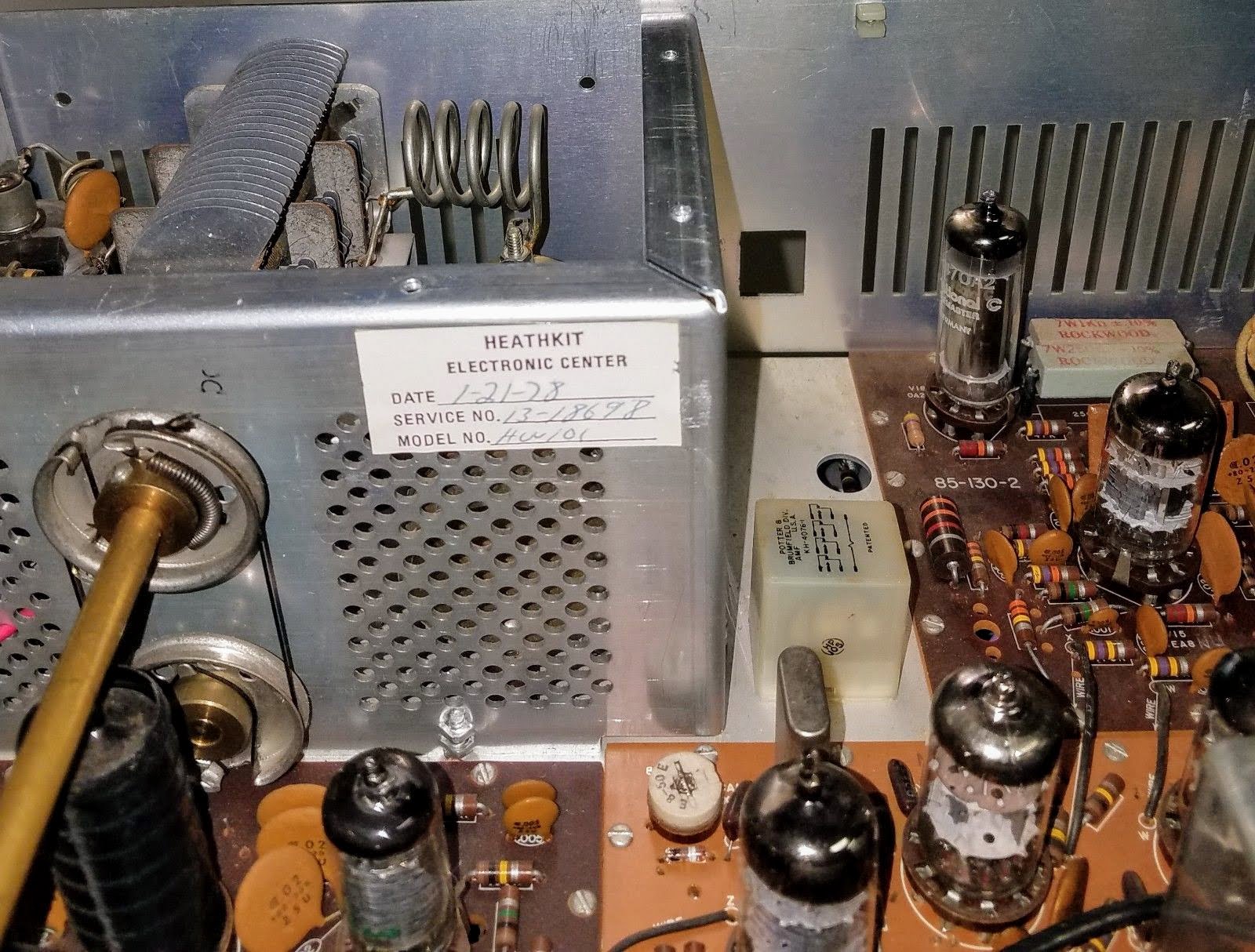
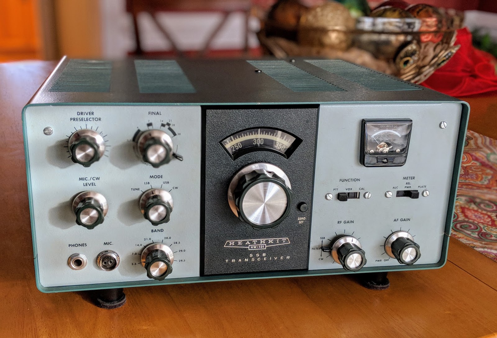
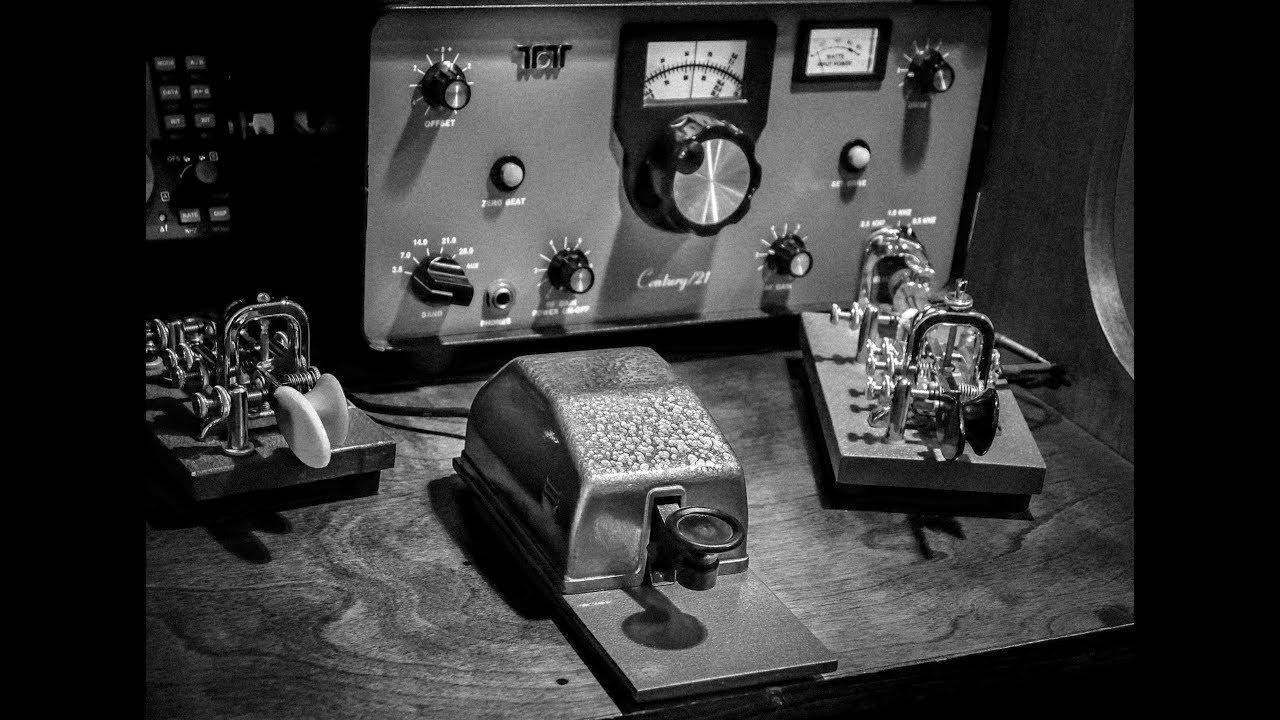
Heathkit HW-101 after it's first QSO under new ownership
I completed my rebuild of my Heathkit HP-23B power supply this morning. There was a bit of frustration on my part as I followed the instructions because they only have photos of a HP-23 which has adjustable bias and no LV switch.
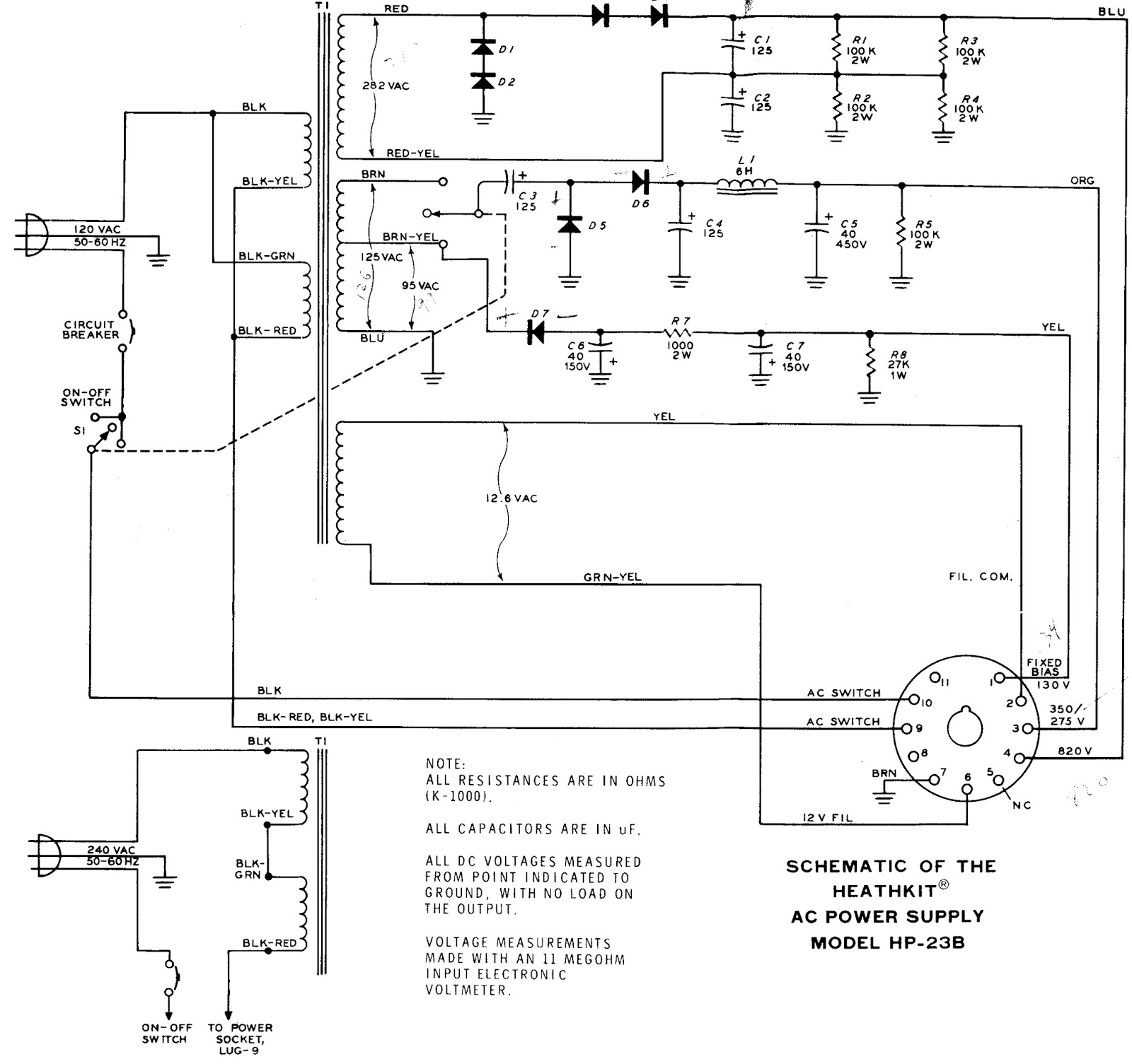
It left me scratching my head a couple times, and I had to locate a schematic of a HP-23B to complete the work.
Heathkit HP-23B Schematic
I really need to learn more about electronics
In the midst of the rebuild I thought I had a problem with the transformer. Both low voltage winding taps (275v and 350v) showed very low resistance (about 5 Ohms) to chassis ground, which led me to believe there was a short in the transformer.
I called my mentor in all things Ham radio, Paul AA4XX, and described the issue. He walked me through the schematic and had me unsolder a couple points to confirm his guess that all was well. That double tap, low voltage winding presents very low resistance to ground but it is not a short in the world of AC. I continue struggling to wrap my head around the differences in AC and DC, but I'm slowly learning and fortunately haven't caught anything on fire yet.
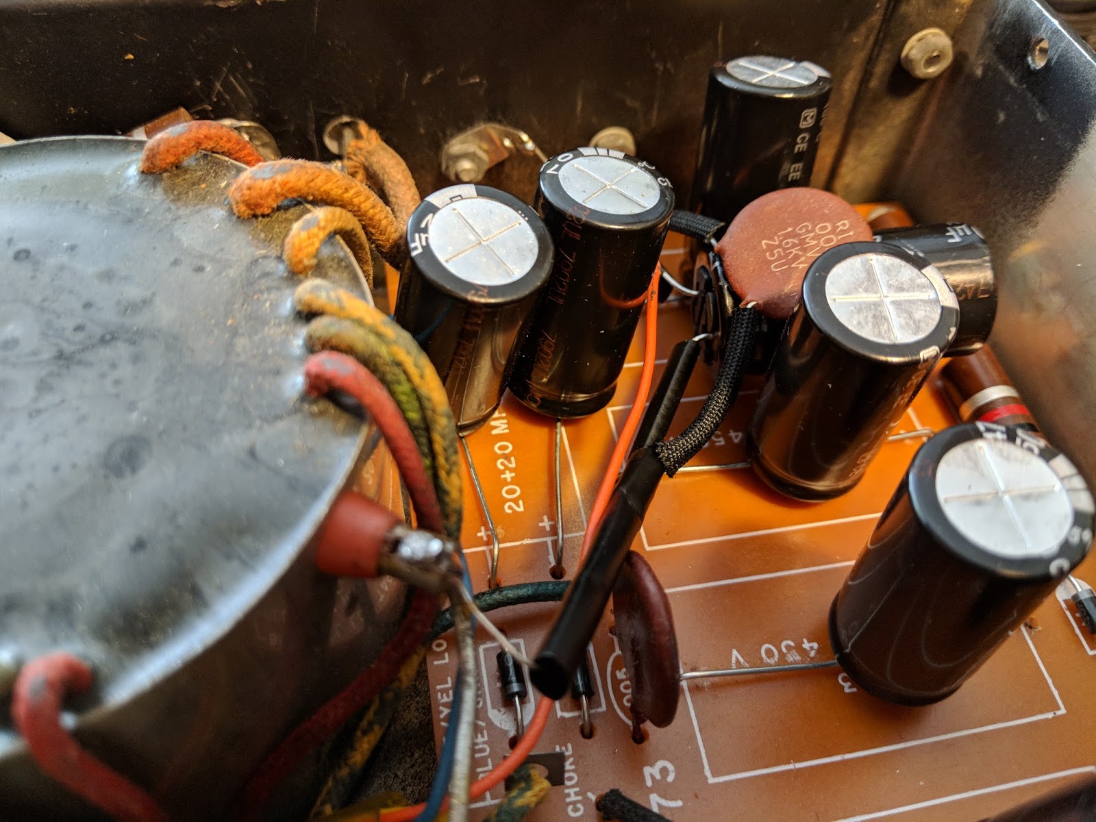
Out with the old, in with the new
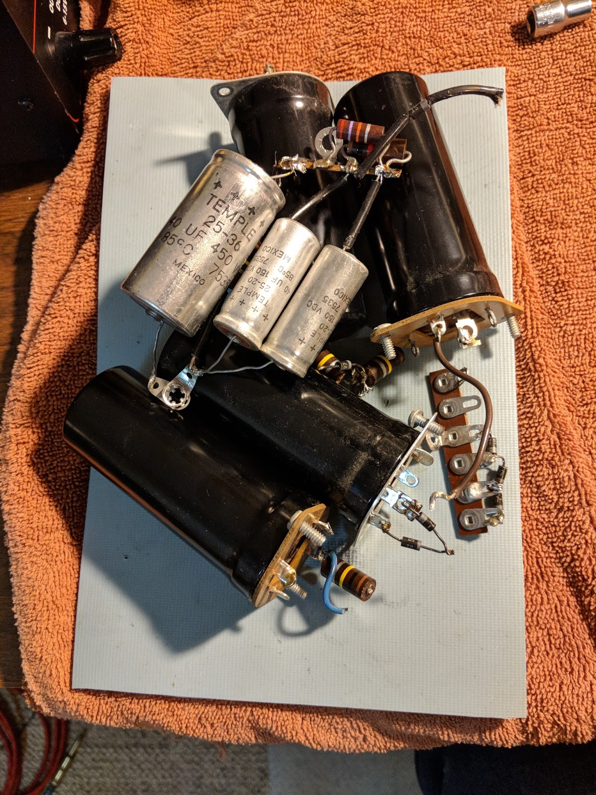
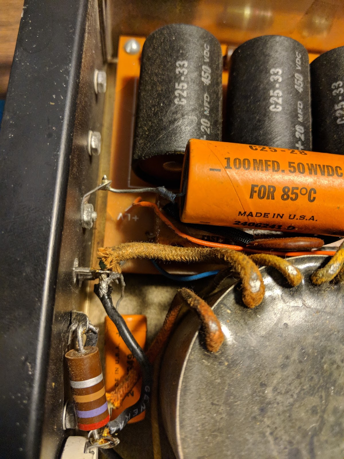
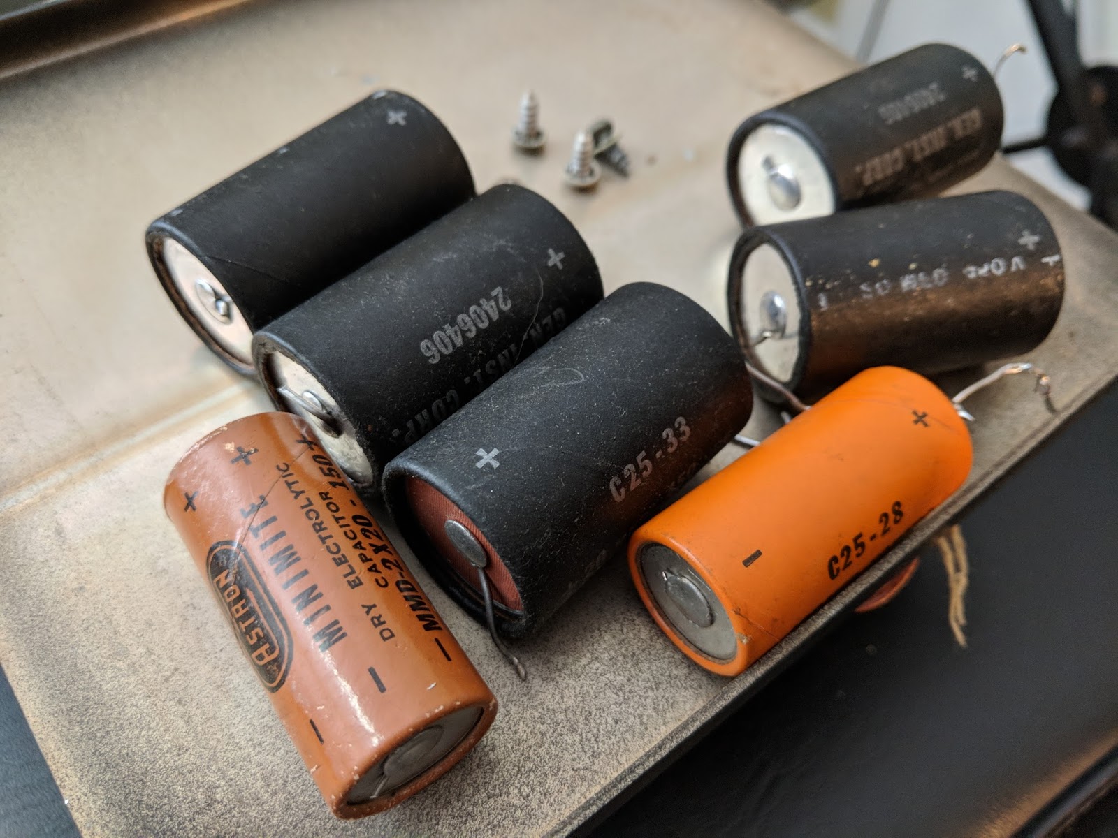
Old components
Testing High Voltage
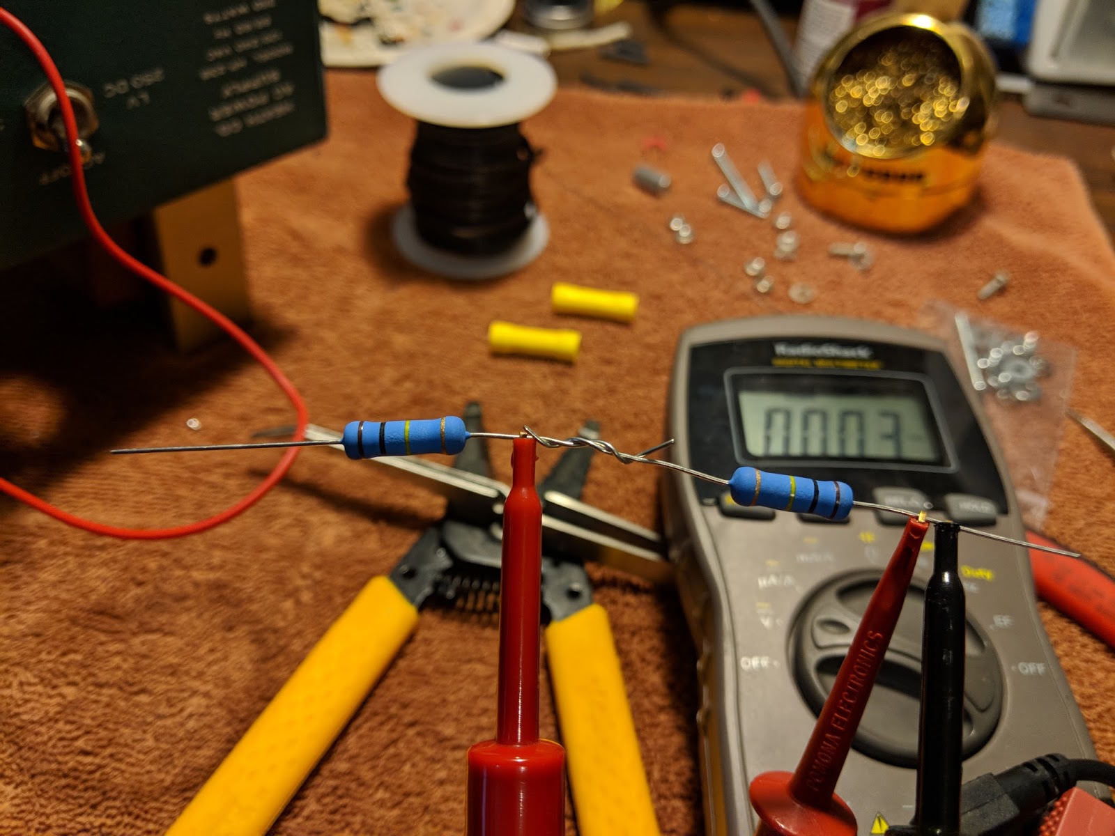
My Multi-meter can only measure up to 600v, so in order to measure the 800v output I used two 3 watt 100 kOhm resistors in series as a voltage divider. When in use, the MM will read half the voltage.
Voltage divider for measuring the high-voltage output
With the voltage divider the HV power measured 401v which works out to 802v undivided
Completed upgrade
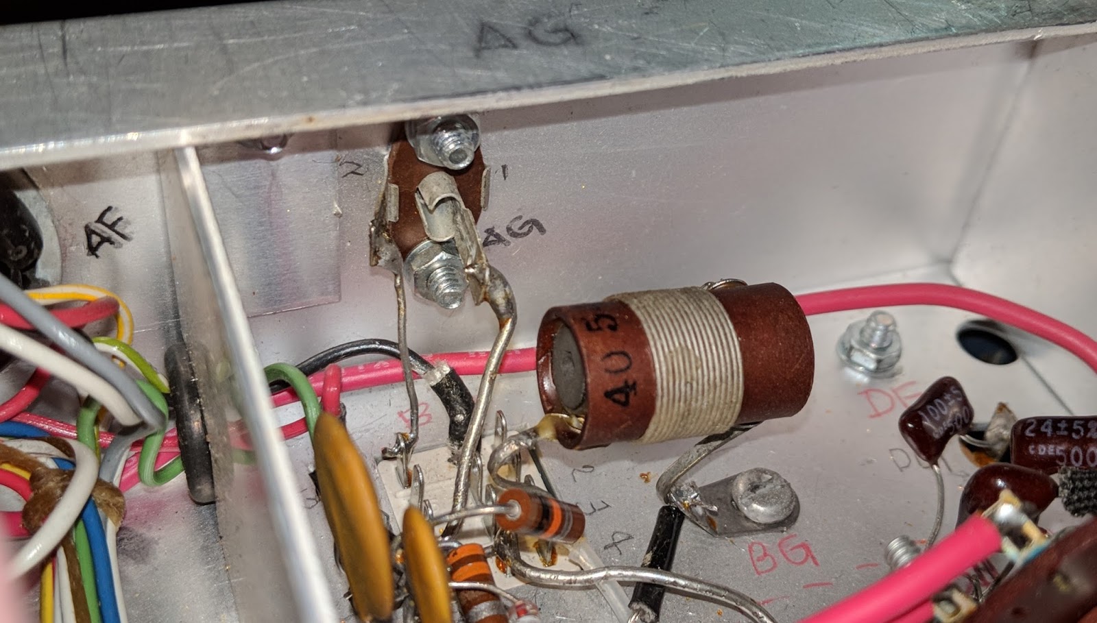
The kit places all the components in the base and the holes that the old big filter capacitors used to be in are now just ventilation. I need to put a wire shield over those holes because high voltages are present just below, as well as some really hot resistors. With the top cover back on it, there shouldn't be a problem but the wire mesh shield is still recommended, especially if it's to be used inside a Heathkit speaker, where the top cover is not used.
With the PCB board, all the components are out of sight in the base except the big resistors
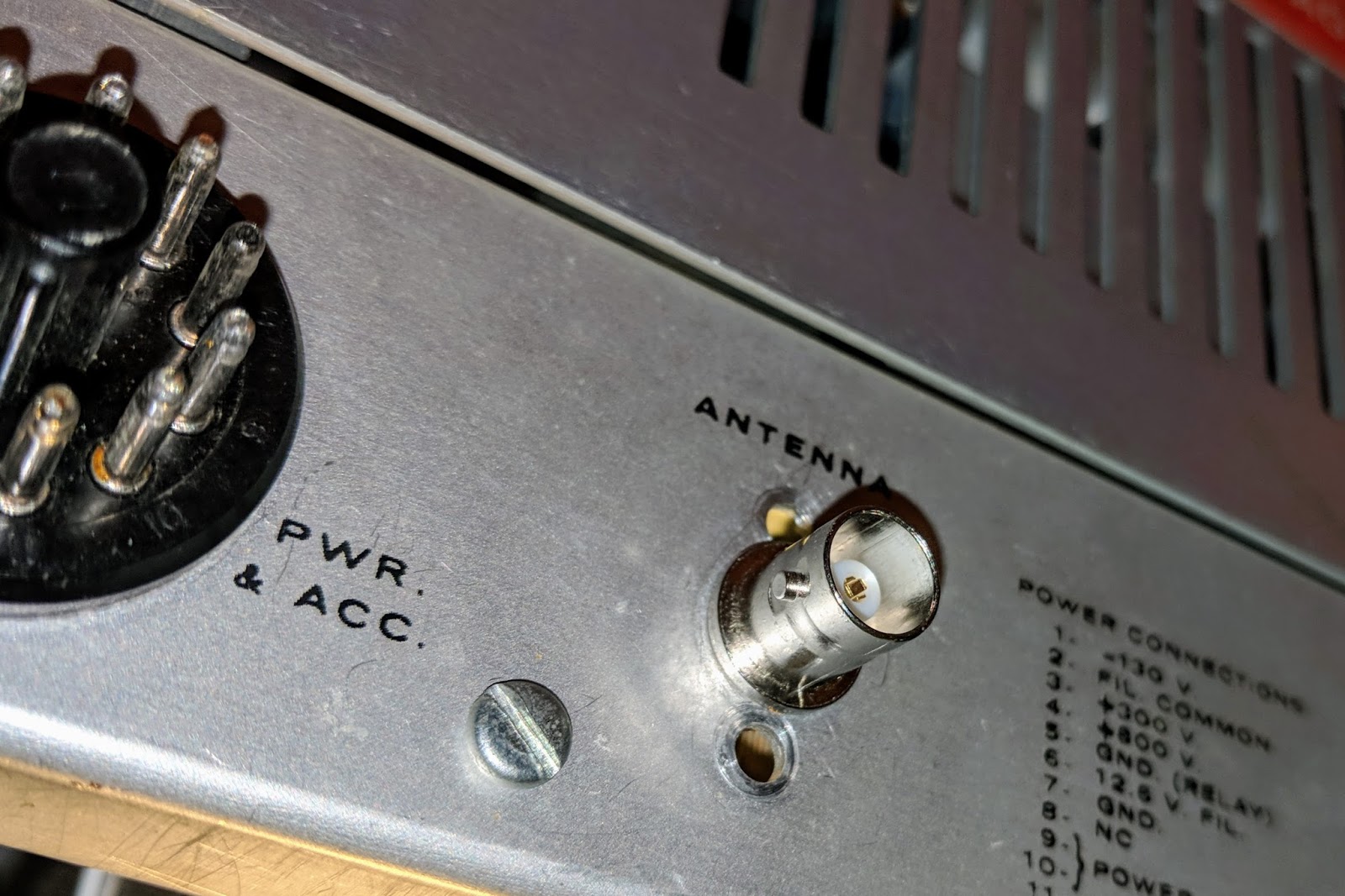
Replaced the HW-101 antenna connector with a BNC
Original antenna connector was a RCA with questionable integrity.
Original RCA antenna jack (viewed from inside chassis)
Replaced with BNC jack which fits without enlarging the original hole.
New antenna jack
The old radio now has power
I replaced the old paper 350v 20uF electrolytic capacitors in the HW-101 and then connected the power cable and switched it on via the switch in the HW-101. I didn't hear any audio at first and thought something was wrong. Silly me, those tubes need a bit to warm up. After a minute I was hearing audio and used the built-in crystal calibrator to check the VFO dial. It was pretty close to spot on.
I ran through some initial checks according to the Heathkit manual. Receive worked well. I listened to some SSB and then dropped down to the 40m CW portion of the band and listened to CW. I waited about 30 minutes for the tubes to warm up. I didn't hear any drift on CW stations I was monitoring.
I found an open frequency, checked the plate current and then tuned up, outputting only about 10 watts because I don't know what state of alignment the finals are in yet. This is the first time I've tuned a tube rig and that was interesting. You have to peak the preselector in receive mode first, then when in tune mode, quickly work back through the preselector, final tune and load levers to peak the RF output. It reads more complicated than it actually is. My OCFD antenna has about a 1.7:1 SWR on 40m so it didn't need much tweaking from the initial settings.
I tuned around and answered N4PGJ, Ron in NY, and had a brief WES exchange. The relay control time set by VOX delay needs to be bumped up a bit as it was dropping between every word break, but other than that it worked like a charm.
I'll make a video soon, but initial impressions are positive. The audio quality was astoundingly good, and the CW filter really did a much better job than I expected. It has a very pleasant sine-wave sidetone rather than the raspy square wave sidetone of my Ten-Tec Century/21. I really think I'm going to enjoy using this old rig.
UPDATE
I got the rig buttoned up and on the desk. Here's a video...
Breath new life into a Heathkit HP-23 power supply
My recent interest in restoring a 1970s Heathkit HW-101 tube radio, is leading me down quite a winding path.
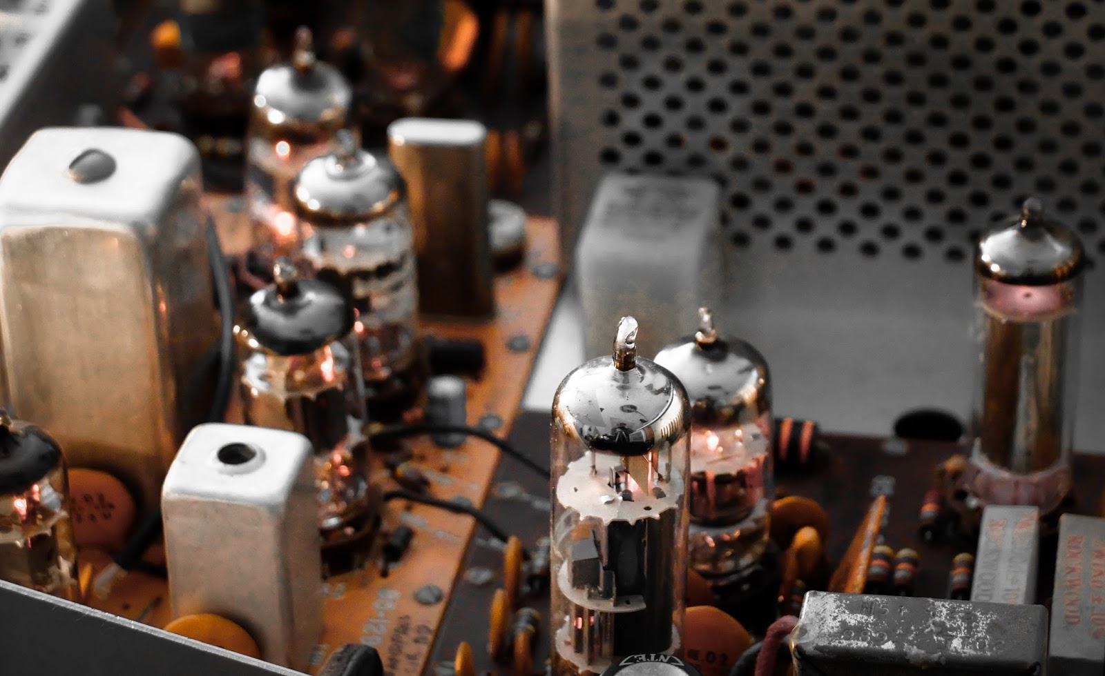
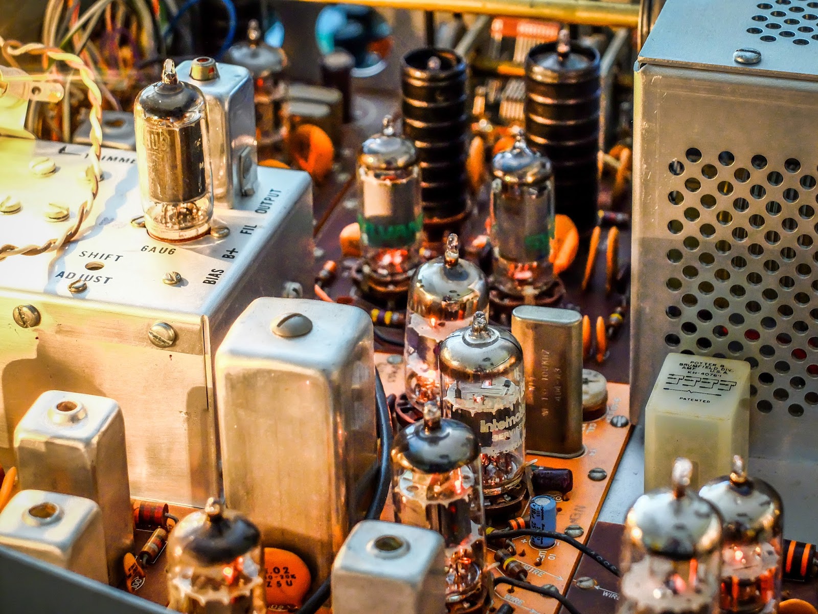
Before I can even test the HW-101 I must be able to supply it with power. Vacuum tube radios need multiple voltages for the different tubes in use. In the case of the 20 vacuum tubes used in the HW-101, it needs the following voltages to operate, 800v, 350v, -130v and 12.6v.
If you've followed previous posts you'd read that I thought I'd be clever (as if), and restore a Heathkit power supply that runs off of 12v so that I could use it mobile or from my 12v linear supply in the shack. Well, I restored a HP-13 and if you read that post and watched/listened to the video you and I now both understand why operators only used those power supplies out of earshot, like in the trunk of their automobile, or in the next county. It makes way too much audio racket to be at my operating position.
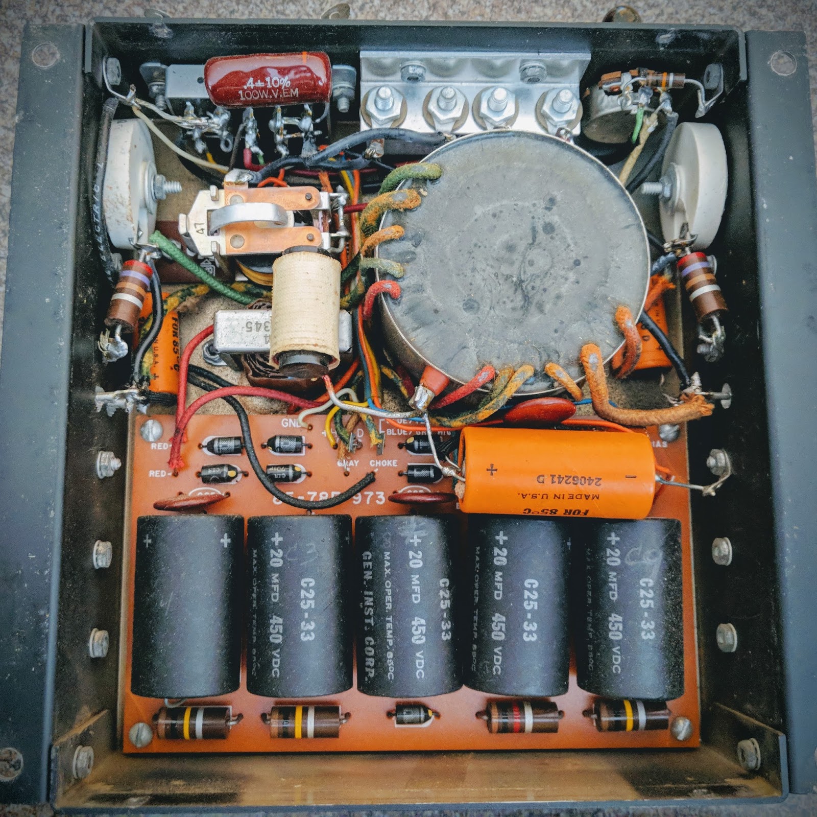
So, pouring a bit more money into this effort, I bought a AC/mains powered supply; the Heathkit HP-23B... but alas it has old components and also needs to be restored.
Heathkit HP-23B
No direct replacement capacitors
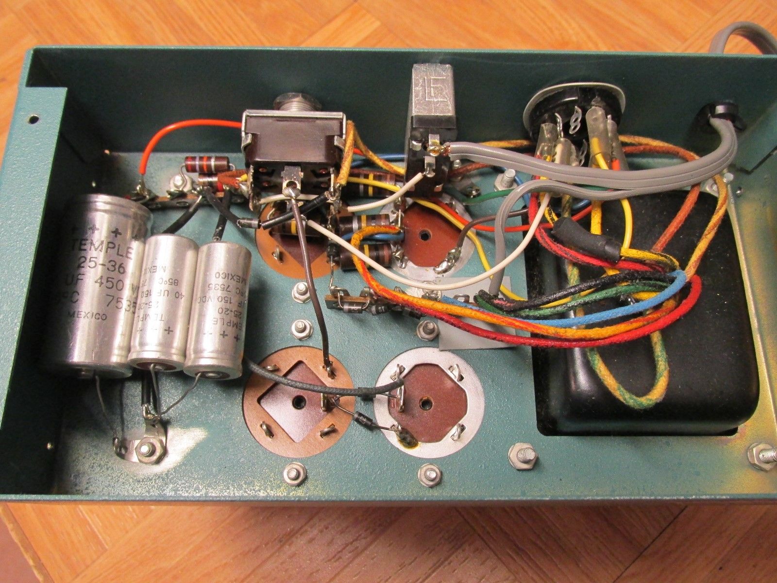
Those large capacitors in the first photo have no modern equivalent in terms of the pin-outs and the HP-23B chassis used some phenolic wafers that are rather fragile after this many years, to hold those capacitors. There are some videos showing how to adapt modern capacitors to fit and that would help maintain it's classic look, but it seemed a bit fiddly to do. Also, you can see that in the base of the power supply there are numerous other axial caps and resistors that need replacing and it's a frightening mess of wiring in there given the voltages present.
Old Heathkit Parts to the rescue
This is such a common issue with these power supplies, that K8GNZ designed a PCB compatible with modern electronic components that would replace that tangle of wiring. It can be ordered from Old Heathkit Parts for a reasonable sum and comes with a CD listing the components that need to be ordered as well as instructions for building the PCB and wiring it up with the HP-23B.
This board gives you one convenient place to populate all the components and hookup the wiring in the HP-23 chassis.
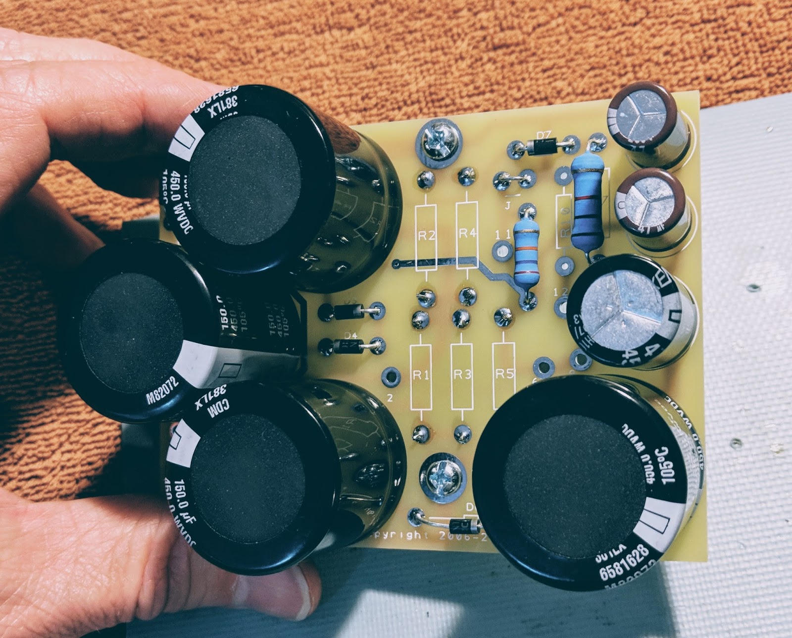
HP-23D PCB
The 3w 100k resistors go on the bottom mounted 1/4" off the board so they don't burn the board (they get hot)
Partially populated board
All done, ready to wire up to the HP-23 transformer and choke
Note how much smaller the 4 new 450v caps are than the ones they replaced in the photo at the top of the post.
The next step is to tear down the old HP-23B and prepare for this board to replace its innards. Maybe this weekend.
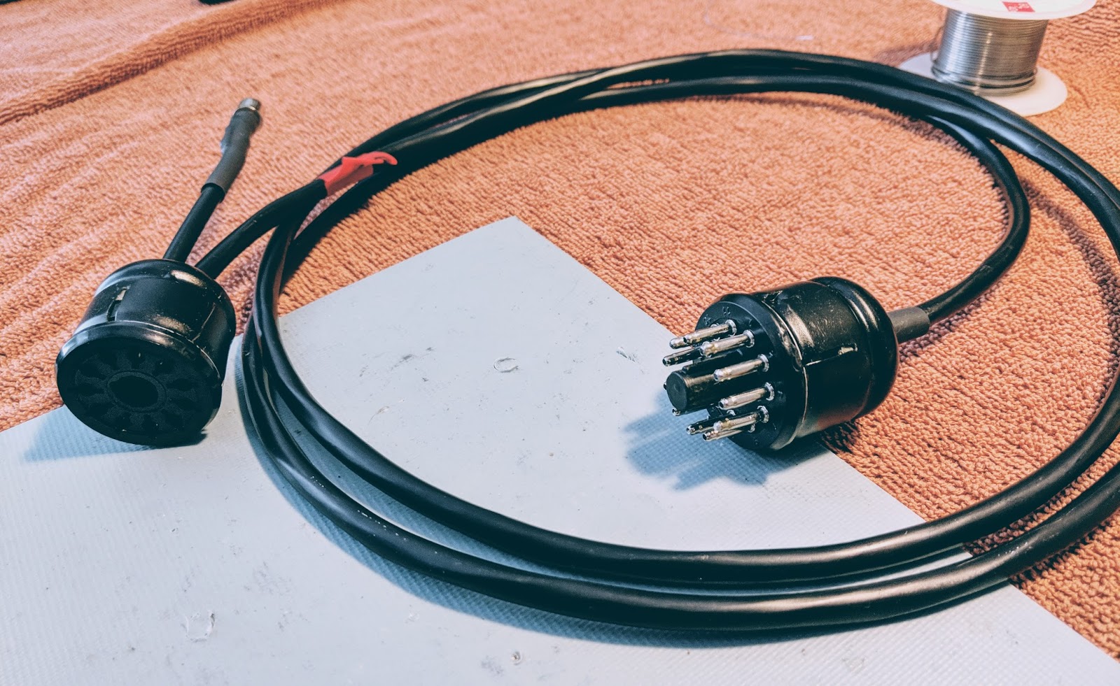
Gotta get the power from the supply to the radio
The power supply has 8 connections to the radio and Amphenol 11-pin plugs are used for the connections. I purchased a wiring kit on eBay that I'm not really pleased with so I won't provide a link to the seller. It works but there were some compromises. If I need another cable I think I'll just find a used one.
Power cable
I also added an amp-key line out from pins 5 (ground) and 11 (relay) for future projects. I terminated it into a female RCA plug. I have previously used the amp-key line from my Ten-Tec Eagle to trigger the protective relay on my SDR, so I may use it for that, or something else. I figured as long as I was soldering 16 connections in those plugs I could solder a couple more.
Amp-key line out
I've also purchased an additional NOS female Amphenol 11-pin chassis plug that I plan to wire up from the Grove connector on the HP-13 so that I can just use the HP-23 cable with the HP-13 if I wish to in the future.
So just a few more hours of work and I should be able to light up the old HW-101 for the first time in decades.
The smell of hot tubes awaits... or magic smoke... I hope it's the former
As seen in my previous post I've taken the dark plunge into the world of tube radios. I want to start restoring my Heathkit HW-101, but before I can do that I must be able to power it. As I previously wrote, I taken the road less travelled and got an old (circa 1965) HP-13 mobile power supply because I thought it would be nice to power the radio from a 12v source rather than mains.
Unrestored HP-13 with broken solder joints and trashed capacitors
Well there seems to be a reason these don't seem very popular... I'll get to that.
I found a very nice article from RDF-Electronics regarding modernizing the HP-13 power supply. That document includes the components and part numbers for everything you will need to restore your HP-13. My parts arrived from Digi-key and I began snipping and desoldering the old component off the PC board. The replacement electrolytic capacitors are all much smaller and have radial rather than axial leads. That makes placing things on the board require a bit more creativity.
HP-13 Schematic
The only truly problematic components to replace was replacing the twin positive axial lead electrolytic (C11) with two electrolytic capacitors (space issue) and replacing the C1 and C12 due to the tricky wiring around the transistors.
The orange cap on the left under the Q1 (C1) was tough to replace with a much smaller radial lead capacitor
The article suggested replacing the original 100 uF/50 V capacitor with a 4,700 uF/35V to better control ripple. The article goes into quite a bit of detail concerning his testing of ripple using an oscilloscope. Finding room for that big cap and it's accompanying filter disc required a bit of creativity as seen below, where it's laying on its side between two of the rectifier caps.
I will glue all the caps to the board before I put the power supply into service.
New capacitors and diodes
I replaced all the electrolytic caps and diodes. The diodes might have been ok but they are blocking over 300 volts each and a single failure would let the smoke out for sure.
Out with the old
In with the new
All the resistors except one 100k 2 watt were ok. So I only replaced that resistor. The 1.6kv disc caps even measured ok.
The internals look a bit different now with the new caps standing up where the old, larger axial lead components laid flat.
Ready for testing
Testing
After performing resistance and continuity checks I buttoned it up for the test.
The Noise
I had no idea how audibly noisy this power supply would be. The switching that occurs in the transformer creates a very loud whine. I understand why hams would install these in the trunk. There's no way you'd be able to stand this for long if it was sitting next to your station.
I have a longish intro in the video. Skip towards the end to hear it powered up... turn your volume down when you see the "hearing protection" sign come up in the video.
Conclusions
This was a good learning experience. I learned about high voltage transformers and got some practice restoring older equipment. I practiced electrical safety and didn't kill myself, so I'm pleased about that.
I now have a power supply I could use from a sturdy 12v source if I needed it, BUT due to the noise in operation I'm going to look into restoring a HP-23 which runs off house mains (AC) and is mostly silent.
I'll keep this on the shelf waiting for a day that I need to run the HW-101 mobile.
A few months after re-entering the hobby in 2015 I picked up a TenTec Century/21. It has been one of my favorite radios to operate and it is the most aesthetically pleasing radio I own. After working with it's older (circa 1977) discrete transistorized technology and debugging some of it's problems, I became interested in building kits to learn about electronics. I built a number of radio kits from different sources and some of the mini-module kits from Elecraft.
But I kept wondering about tube radios. I came to the hobby well past the tube radio era and although I've read a lot about valve technology I didn't have any first hand experience. I kept watching auctions for old Heathkits and Military radios and even bid on a few but lost the bids.
This past Christmas I decided that in 2018 I'd do something about this lingering interest. I knew I'd eventually want to operate one mobile because, well that would certainly make it harder. The power requirements of tubes are orders of magnitude greater than the QRP transistorized rigs I'd purchased. Not knowing what I was doing I figured I could re-work an old Heathkit HP-13 power supply to give me what I'd need for an old military radio like the GRC-9.
Heathkit HP-13a
Unsurprisingly, I was the only bidder and got one for $30 along with the odd grove power connectors that it uses. But I didn't do my research, and soon learned that the magic for these high voltage power supplies lies in the very specific design of their transformers. In the case of the HP-13 it is operated much like an old military vibrator power supply with two germanium transistors acting as the vibrator. Current is applied to to the core until it saturates and then a specific voltage determined by the number of turns is generated, the saturation drops the current to that winding and it starts over with the other transistor and the other winding. I couldn't easily, or practically lower the 800v high voltage down to 580v required by the military radio I wanted and even the low voltage windings produce 300v and 250v respectively which is far beyond the 105v needed by the military radio.
I was warned off actually purchasing a military vibrator power supply due to a number of issues so I decided I'd start out with the radio this supply was designed for, a Heathkit HW-101. All the electrolytic capacitors have to be replaced, and I plan to replace the diodes to be on the safe side as well. I'm hoping the old transistors are still serviceable as I can't find any information on direct replacements for those. I've ordered the replacement caps, diodes and resistors so I'll see how my refurb of this old power supply works out. Working with voltages that can kill me is a bit daunting and I'm being very careful with the limited power-up tests I've performed so far.
Heathkit HW-101
That brings me to the newest arrival. If you read my blog you know I like to do photography and it's no fun to photograph ugly radios so I kept watching auctions for HW-101s that were in good cosmetic condition. I knew I'd have to do a good bit of refurbishment on whatever I ended up with but at least I could start with a "looker".
Heathkit HW-101
I plan, of course, to use it primarily for CW. I'm aware that this radio is NOT particularly pleasant for CW due to the clacking relay as well as the poor filtering, but I've gotten accustomed to hearing lots of CW stations at once while working with my Century/21 so I think I can adapt. All my other radios have full break-in so this will be a challenge to deal with, but I'm up to seeing what it was like for old time hams.
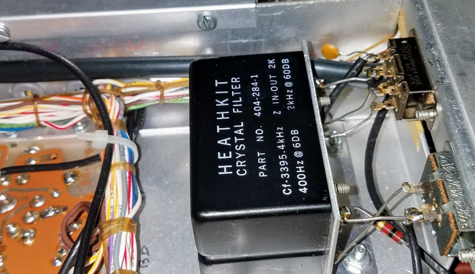
Crystal filter
While it has a crystal filter, 6dB of filtering at 400Hz will not offer much rejection to the out of band signals. I guess I'll see.
Admittedly this is far from QRP radio but I will endeavor to operate mobile at least a few times just for the experience. I plan to operate at QRP levels to the extent I'm able. There's just so much for me to learn.
If I don't maim myself or burn my house down, be on the lookout for posts as I resurrect the power supply and the old girl and get it on the air. I have some ideas for photography involving glowing tubes that I think will be fun to figure out. My bigger challenge is that I have no room for this thing at my operating position, so I'm trying to figure that out as well.
So drop me a line if you have restoration experience with these rigs. Of course I'm reading what I can and look forward to learning how to align the transmit tubes and all the things I've had absolutely no experience with in the world of transistorized radios.
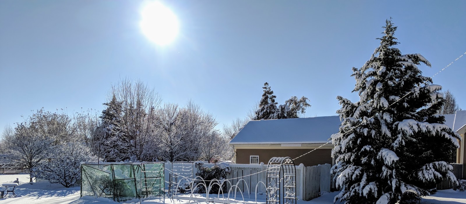
We aren't supposed to get this much snow in central NC
We received a remarkable amount of snow yesterday here in central NC, my antenna iced up and looked very pretty, then the wind picked up and my antenna fell down. Boo-hiss !
My homebrew OCFD antenna is constructed from donated, surplus, lightweight doorbell type wire attached to a 4:1 current balun in a PVC tube with threaded nuts to hold each end of the dipole on top and a coax connector on the bottom. An eyelet through the top of the balun suspends it all via some 10 year old dacron rope (dacron rope is amazing stuff), which is attached to the eave at the peak of my roof.
How, pray tell did I get the rope attached to the peak of roof 33 feet up in the air you ask, having no tall ladders or Spiderman abilities? I'm glad you asked... Well, the rope is tied inexpertly, using granny knots, to one side of an S-hook. I use a cane-pole fishing rod as an extension with a piece of masking tape on the end lightly holding the S-hook. Then I precariously lean out my 3rd story window eight feet under the eave (don't try this at home) and "fish" the S-hook through a loop at the peak of the eave, that was installed there by my nice painter, many years ago. Once the S-hook is in the loop, I tug on the fishing pole and the masking tape lets loose of the S-hook and the S-hook remains in the loop, holding a few feet of old dacron rope. QRP-indeed !
This incarnation of the antenna was first installed November 2015. In that time an ice storm drug it to the ground, and a tropical storm broke the mooring as well.
Amazing stuff, doorbell wire and old dacron rope.
That gleaming line of ice from right to left in the picture below used to be elevated a bit more
Even with my outdoor antenna down, I was able to make a contact on 80m last night using the 68'ish foot long doublet in my attic so wasn't completely incommunicado. It shouldn't be hard to get the OCFD operational again. A bit harder will be repairing the blueberry cage that collapsed under the weight of snow on top of the netting.
This antenna is designed to fail gracefully
I wanted to be sure that when the antenna was under stress it would relieve itself at the easiest place to repair. The rope on the long end of offset dipole runs through a pulley attached, with a zip tie, at the top of a set of sturdy, stacked fiberglass tent poles. The rope runs through the zip-tie attached pulley to a long, lightweight, spring (the kind used for a small fence gate) along with the pulley provides the strain relief when it's windy. The zip tie holding the pulley at the top of the pole is intentionally the weak link. When the forces become too much the zip tie breaks and the long, heavy side of the antenna falls across the garden. It's a simple matter to pull a section of the fiberglass pole loose, attach a new zip tie, and Bob's your uncle.
So when you design your next wire antenna, plan ahead for easy repair.
That's all for now...
So lower your power and raise your power... and antennas after they fall