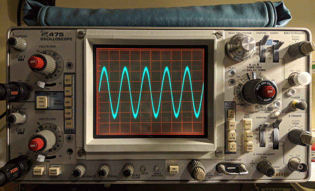
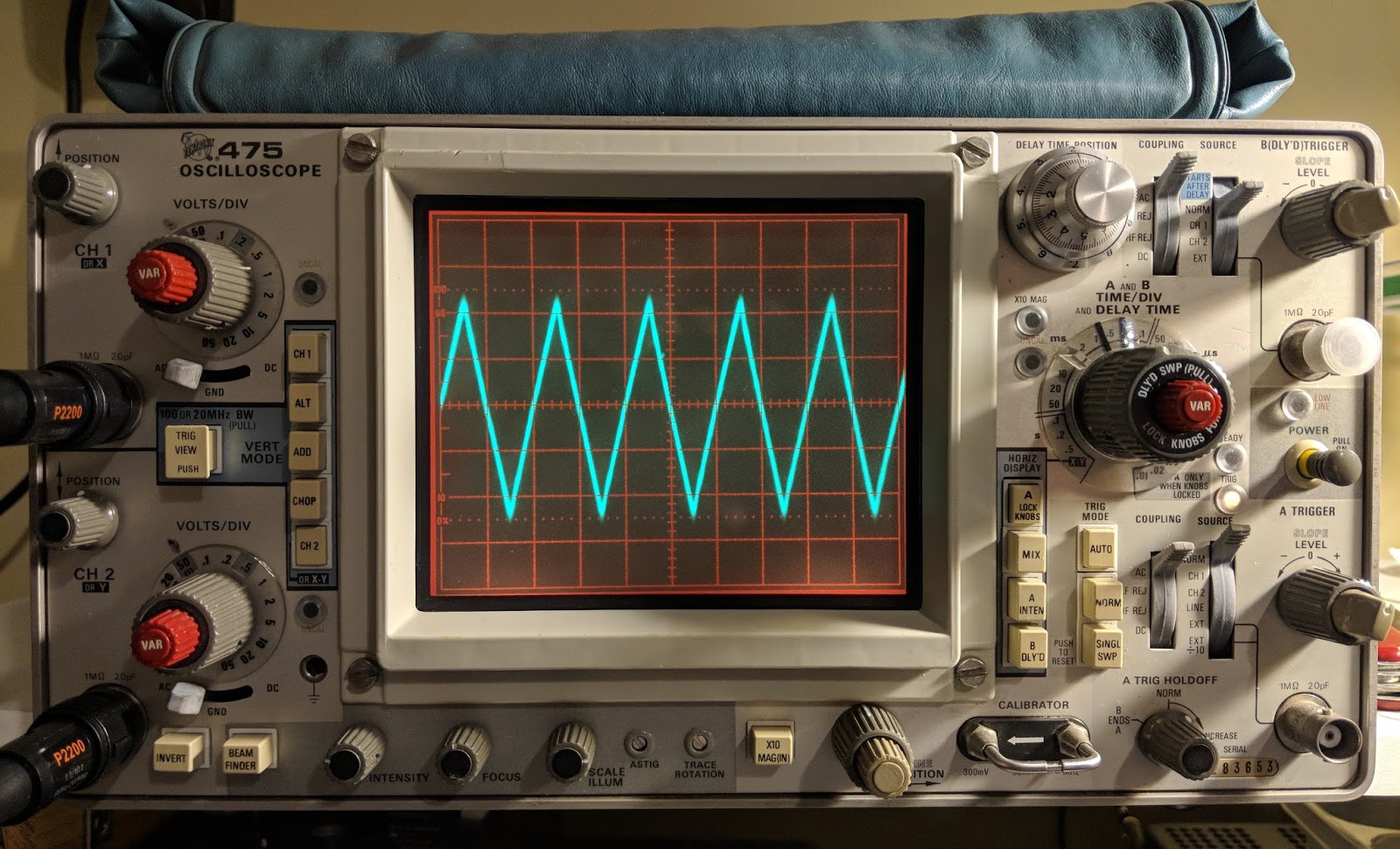
Tektronix 475 Oscilloscope and Android Signal Generator App
When I was debugging problems with my Ten-Tec Century/21, and especially my problematic one-watter kit, I needed to see more than DC voltages. I carried my problem stuff to my friend Paul to see what his scope and signal generator revealed.
Why would a ham need a scope? Audio and RF are both AC (alternating current) and a voltmeter alone doesn't offer much insight into that world of voltage across time and phase.
I almost bought an inexpensive digital scope last year, then thought better of it. Then I almost bought a featured digital scope and checked my wallet and thought better of it. A good digital scope in the 100 Mhz and up range from reliable sources costs upwards of $500. On the other hand, older professional scopes that have been well maintained and kept in calibration are excellent choices and will last a lifetime. You do give up handy on screen cursors for measurements, so you have to count divisions by hand and do the math. You also don't have digital storage in a digital scope, but smart phone cameras and video can make up for that.
When I saw this recently calibrated Tektronix 475 listed in the classifieds on eHam.net for a nice price, I decided it was time to step into the world of visualized AC.
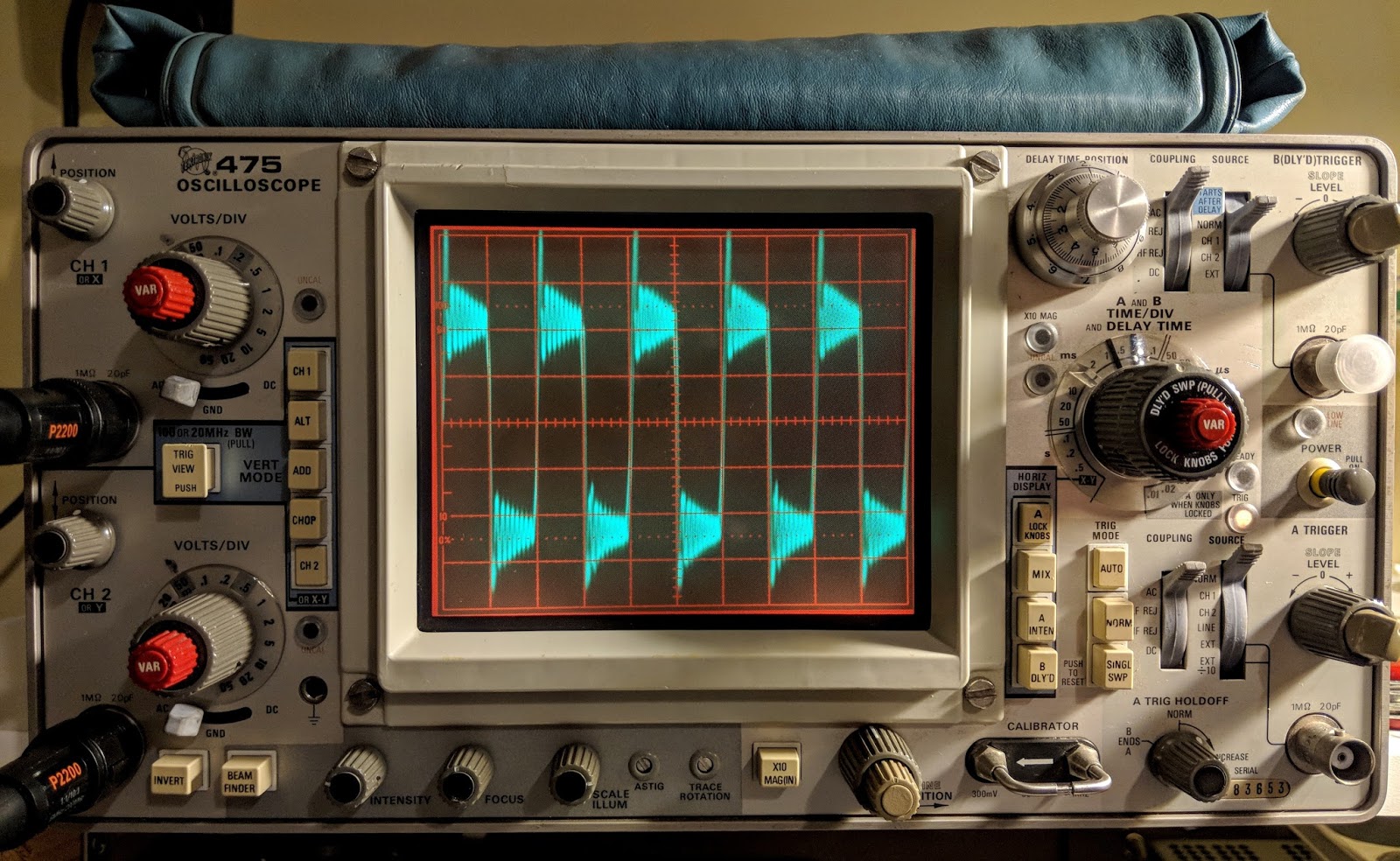
Watching a capacitor charge 250 times a second
The lines are a bit wide because the signal source was noisy
Tek 475 Specs
The Tektronix 475 is a portable (30 lbs), dual-trace oscilloscope with dual time-bases similar to the 465, but with 200 MHz bandwidth and a maximum vertical sensitivity of 2 mV/Div. It is all solid-state except for the CRT. It was introduced in November 1972.
This scope cost $3,000 when it was new. Now you can find them in good condition for less than $200.
Cascaded mode -- 400 μV/Div, 50 MHz with CH1 input connected to CH2 VERT SIG OUT
Time base -- 10 ns/Div to 500 ms/Div, 1-2-5, and ×10 magnifier
Input impedance -- 1 MΩ // 20 pF
Triggering -- 0.3 Div (int) or 50 mV (ext) to 40 MHz, increasing to 1.5 Div/250 mV at 200 MHz; AC coupling >60 Hz; LF REJ >50 kHz, HF REJ <50 khz="" li="">
X bandwidth -- 3 MHz
Z axis input -- 5 Vp-p, 50 MHz
Calibrator -- 1 kHz, 30 mA / 300 mV square wave
Outputs -- CH2 Vert Signal Out, 20 mV/Div into 1 MΩ or 10 mV/Div into 50 Ω; A and B +GATE OUT, +5 V; Probe power jack
CRT -- 8 × 10 cm², P31 phosphor (P11 opt.)
Power -- 110, 115, 120, 220, 230 or 240 VAC ±10%, 48-440 Hz, max. 100 W
Real knobs and switches
One advantage of an analog scope is that there is a labeled switch or knob for every function. No need to dig through menus to figure out how to do something. To me this is the a true advantage to finding a well calibrated, analog scope.
An oscilloscope needs a function generator
An scope let's you visualize AC within a circuit, but when you testing something you often need to inject AC into that circuit. That's the role played by a function generator. Function generators allow you to choose a frequency and a wave type (sine, triangle, square, etc.), or sweep across frequencies.
In general, the higher the frequency they support the more they cost.
If you have a mobile device you can get one that uses your headphone jack as output up to 22 kHz for free...
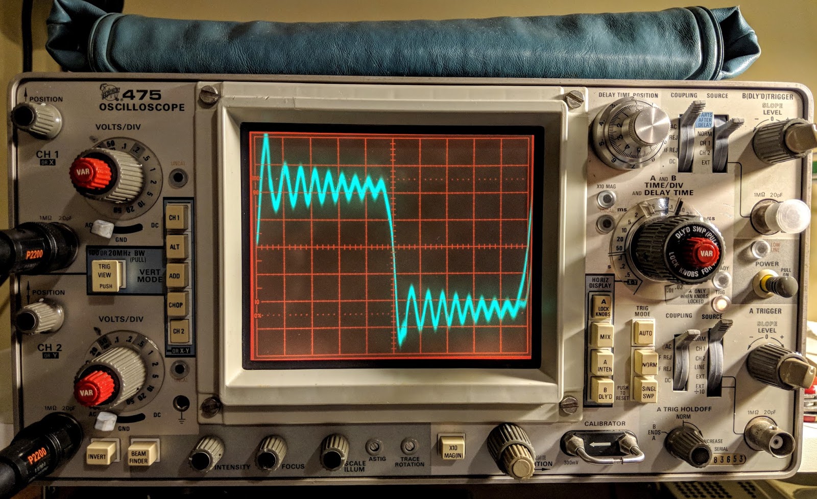
For a free app it is very nice. It outputs sine waves very well, triangle waves are a bit soft pointed and square waves are for entertainment purposes only. But it is free so I won't complain. In the image below you can see the oscillations as it tries to generate a square wave but the audio amplifier of the mobile device just doesn't have that kind of control.
Frequency Generator App set to 1 kHz
Square Wave?
Square waves are not
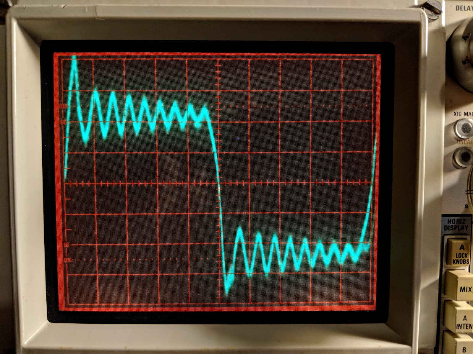
Reduce the time base to zoom in
Yea, square wave.... not so much
The square wave is bad but sine and triangle waves look good until the frequency get's near the top of the range or the amplitude is raised too high.
Sine Waves look good
Triangle waves are on as well until you go up in frequency
The free app is inadequate for bench testing
While I appreciate that this would be a useful, portable signal generator for testing audio circuits, I'll be ordering a purpose-built function generator because generating clean square waves is an important test signal to be clean. I also will need a generator that works above audio frequencies, hopefully up the the IF frequencies of the some of the equipment I'm testing.
Only the beginning
Having an oscilloscope is a new adventure for me. I have another 1-watter kit ready to build that I've been holding off on because I wanted a scope for troubleshooting. In the meantime I'm using the scope to watch transistors trigger and measure the timing circuits I'm building and learning how to control the scope. The Tektronix 475 is a feature-rich analog scope. If you plan to fix your own equipment or do some homebrew electronics work a scope can come in handy.
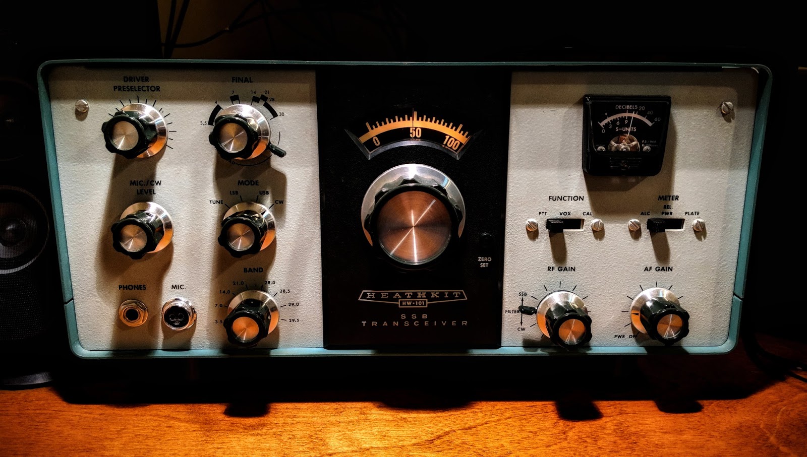
Heathkit HW-101 after it's first QSO under new ownership
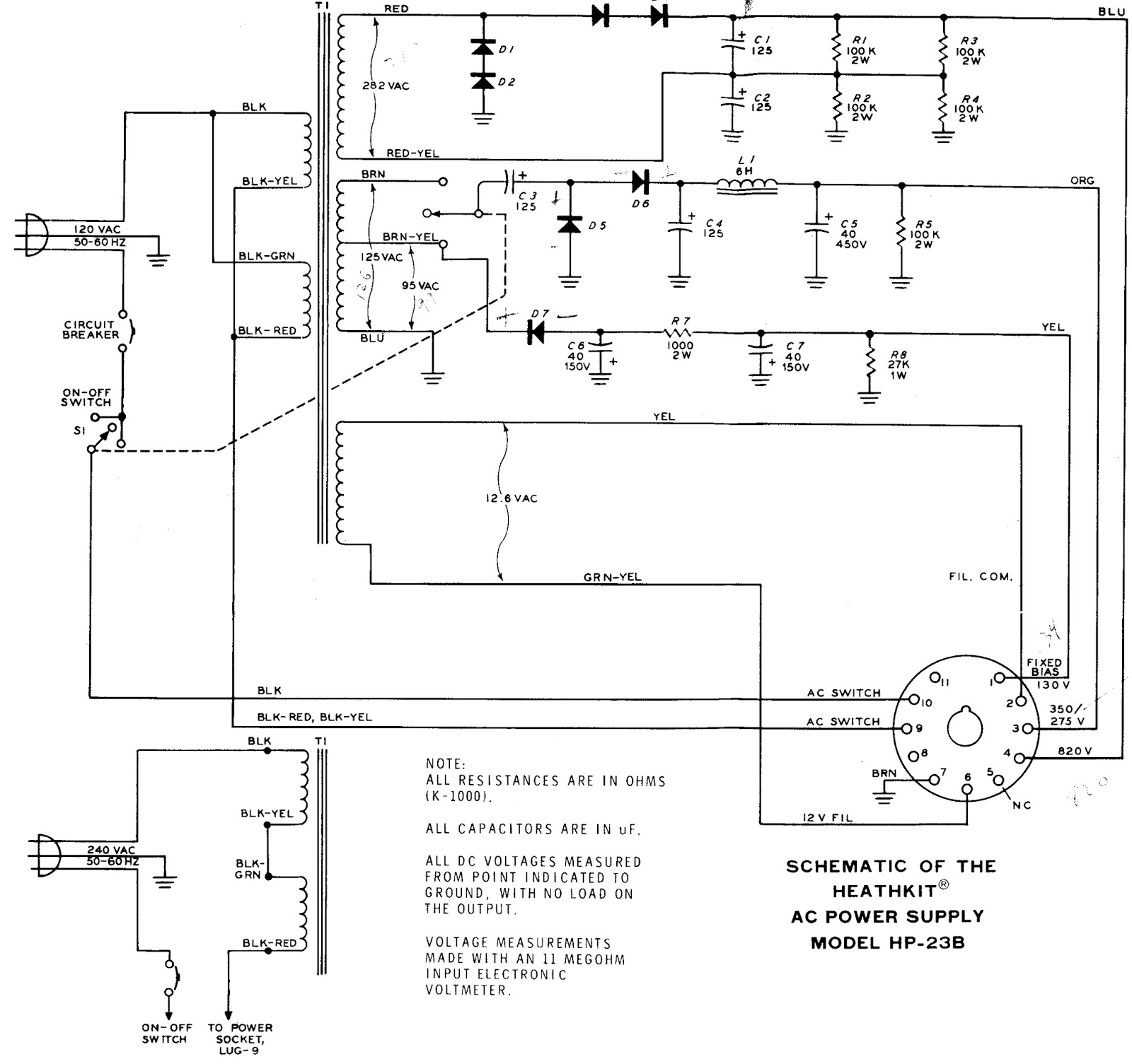
I completed my rebuild of my Heathkit HP-23B power supply this morning. There was a bit of frustration on my part as I followed the instructions because they only have photos of a HP-23 which has adjustable bias and no LV switch.
It left me scratching my head a couple times, and I had to locate a schematic of a HP-23B to complete the work.
Heathkit HP-23B Schematic
I really need to learn more about electronics
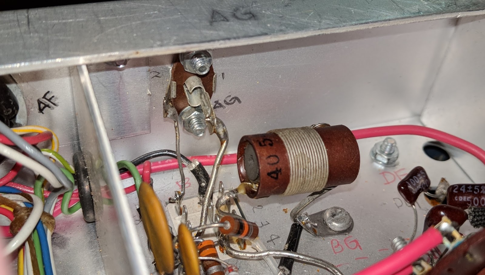
In the midst of the rebuild I thought I had a problem with the transformer. Both low voltage winding taps (275v and 350v) showed very low resistance (about 5 Ohms) to chassis ground, which led me to believe there was a short in the transformer.
I called my mentor in all things Ham radio, Paul AA4XX, and described the issue. He walked me through the schematic and had me unsolder a couple points to confirm his guess that all was well. That double tap, low voltage winding presents very low resistance to ground but it is not a short in the world of AC. I continue struggling to wrap my head around the differences in AC and DC, but I'm slowly learning and fortunately haven't caught anything on fire yet.
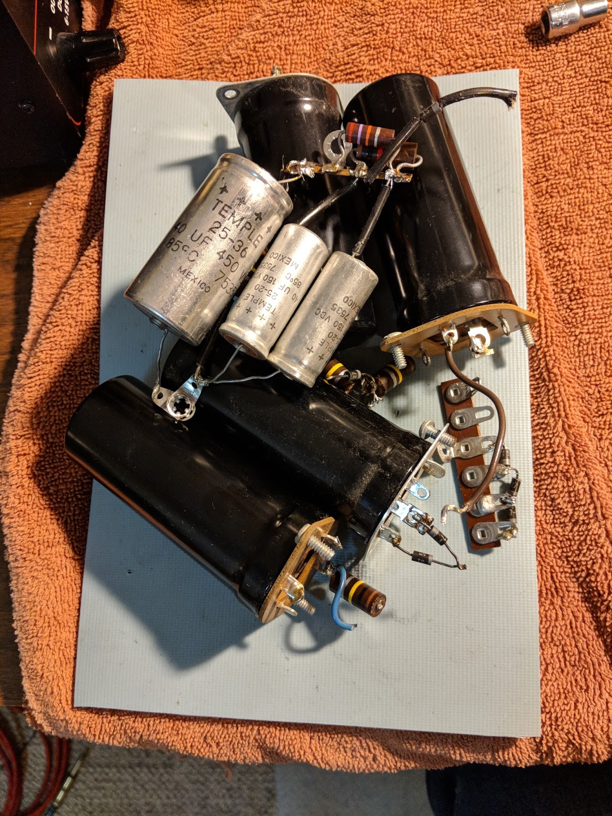
Out with the old, in with the new
Old components
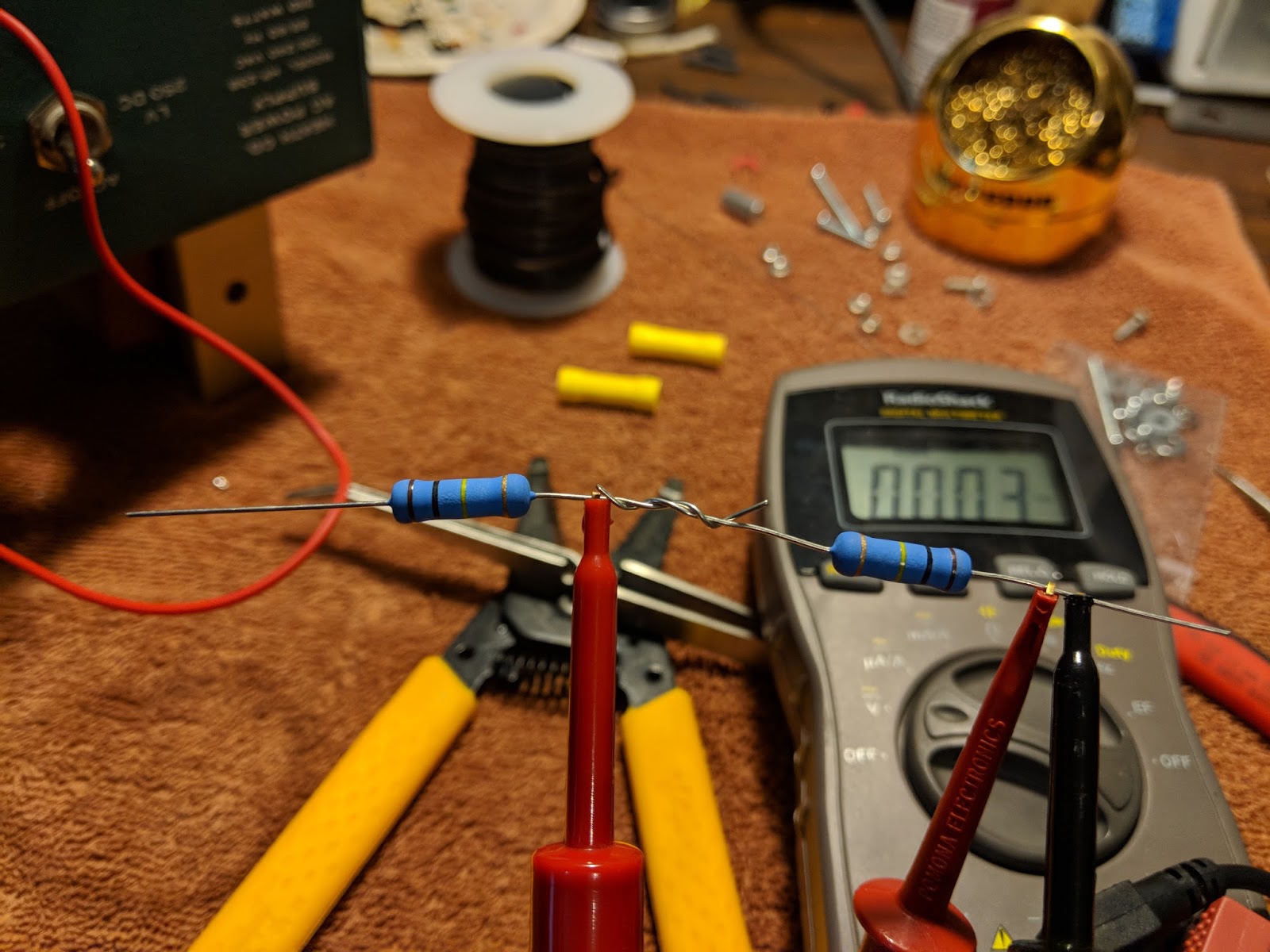
Testing High Voltage
My Multi-meter can only measure up to 600v, so in order to measure the 800v output I used two 3 watt 100 kOhm resistors in series as a voltage divider. When in use, the MM will read half the voltage.
Voltage divider for measuring the high-voltage output
With the voltage divider the HV power measured 401v which works out to 802v undivided
Completed upgrade
The kit places all the components in the base and the holes that the old big filter capacitors used to be in are now just ventilation. I need to put a wire shield over those holes because high voltages are present just below, as well as some really hot resistors. With the top cover back on it, there shouldn't be a problem but the wire mesh shield is still recommended, especially if it's to be used inside a Heathkit speaker, where the top cover is not used.
With the PCB board, all the components are out of sight in the base except the big resistors
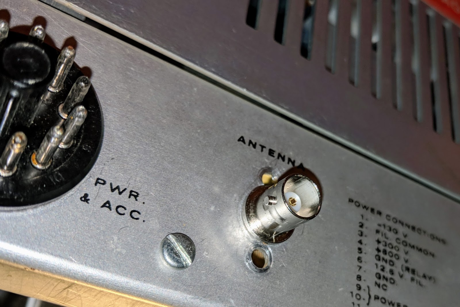
Replaced the HW-101 antenna connector with a BNC
Original antenna connector was a RCA with questionable integrity.
Original RCA antenna jack (viewed from inside chassis)
Replaced with BNC jack which fits without enlarging the original hole.
New antenna jack
The old radio now has power
I replaced the old paper 350v 20uF electrolytic capacitors in the HW-101 and then connected the power cable and switched it on via the switch in the HW-101. I didn't hear any audio at first and thought something was wrong. Silly me, those tubes need a bit to warm up. After a minute I was hearing audio and used the built-in crystal calibrator to check the VFO dial. It was pretty close to spot on.
I ran through some initial checks according to the Heathkit manual. Receive worked well. I listened to some SSB and then dropped down to the 40m CW portion of the band and listened to CW. I waited about 30 minutes for the tubes to warm up. I didn't hear any drift on CW stations I was monitoring.
I found an open frequency, checked the plate current and then tuned up, outputting only about 10 watts because I don't know what state of alignment the finals are in yet. This is the first time I've tuned a tube rig and that was interesting. You have to peak the preselector in receive mode first, then when in tune mode, quickly work back through the preselector, final tune and load levers to peak the RF output. It reads more complicated than it actually is. My OCFD antenna has about a 1.7:1 SWR on 40m so it didn't need much tweaking from the initial settings.
I tuned around and answered N4PGJ, Ron in NY, and had a brief WES exchange. The relay control time set by VOX delay needs to be bumped up a bit as it was dropping between every word break, but other than that it worked like a charm.
I'll make a video soon, but initial impressions are positive. The audio quality was astoundingly good, and the CW filter really did a much better job than I expected. It has a very pleasant sine-wave sidetone rather than the raspy square wave sidetone of my Ten-Tec Century/21. I really think I'm going to enjoy using this old rig.
UPDATE
I got the rig buttoned up and on the desk. Here's a video...
QRP operators strive to make the most out of a little. So when we receive a signal report it means a lot to us. But the common signal report, given using the R-S-T System, seems often to be misunderstood by some amateur radio operators.
RST has 3 elements:
R stands for Readability. How easy or difficult is it to copy the characters or words being sent on a scale from 1 to 5, with 1 meaning unreadable ranging up to 5 meaning perfectly copy-able.
S stands for Signal Strength. How strong is the signal on a scale from 1 to 9, with 1 being barely perceptible up to 9, being extremely strong.
T stands for Tone. This is only used to describe a CW signal's tone. Given modern transceivers there are few cases where you'd send anything other than a 9 meaning perfect tone, devoid of ripple or modulation. You'll rarely hear a report with a Tone report other than 9, but if you hear ripple or modulation artifacts you may send lower numbers but it will likely just confuse the other operator. If you hear chirp (a rising or falling tone) you may wish to append a 'C' to the RST to indicate that.
I want to concentrate on Readability and Signal strength.
Readability
I believe most of us are guilty of focusing on the signal strength portion of the report rather than readability. But readability can convey a lot to the operator receiving the report.
For instance if you have a lot of local noise or if the band is noisy due to magnetic disturbance or there's QRM or QRN readability may be difficult. Similarly, if the operator is using poor technique and running letters or words together that affects readability.
It's possible that signal strength may be good or even moderately strong (6 or 7) but for some reason copy is difficult. It would be worthwhile to send a 2 (Barely readable, occasional words distinguishable) or a 3 (Readable with considerable difficulty) for the 'R' portion of the signal report as in 359. Then follow up with WITH QRM or WITH POOR SPACING, to make the other operator aware that you're having trouble copying.
I will occasionally have an operator send me a 3 for R but it seems to always be related to low signal strength. If someone sends you a 3 or a 4 and it's not followed by an equally low signal strength number inquire as to the difficulty in readability. It may be something you can correct on your end.
Signal
Signal seems obvious but it's not.
I believe that many operators use the reading on their S-meter to report the Signal strength but different manufacturers calibrate their S-meters quite differently. The difference between S-units is supposed to be 6 dB but that's often not the case. On many rigs the use of the preamp or the attenuator also effects the displayed S-meter reading. So the S-meter is not an accurate reflection of what Signal strength is supposed to convey.
My old Ten-Tec Century/21 doesn't even have an S-meter. Neither do my homebuilt QRP radios.
So, what should we be using? Well how about the actual meaning of the system:
Faint—signals barely perceptible
Very weak signals
Weak signals
Fair signals
Fairly good signals
Good signals
Moderately strong signals
Strong signals
Extremely strong signals
Obviously this is a subjective report, but on my KX3 my S-meter may read 2 when the signal actually sounds Good (6), so I send a 6 even though the meter reads 2. If I were to send the other station the S-meter reading of 2 they'd assume I'm barely copying them, because I sent them a 529.
I think you can start to see the point. Use the system as it was designed, before radios had S-meters and the Signal report will have more meaning to the station receiving the report.
My Ten-Tec C21 doesn't have an S-meter but it does have AF and RF gain controls. I will commonly run my AF gain at a high level and use the RF gain to control the volume of the received signal. This increases the SNR (signal to noise) and gives me a relative gauge of how strong the sender is. If I have my RF gain turned all the way down and still clearly hear the other station they have an extremely strong signal (9). If I have to turn my RF gain all the way up just to copy then the signal is very weak, or faint (2 or 1). In between those extremes I offer a relative report based on the signal strength I am hearing.
So, use the system as it was intended
So, reconsider how you give a signal report. Think about the original intent of the R-S-T System and you'll be conveying far more information in your report that may help the other station know for certain how they are being heard.
I start most QSOs at QRP levels. If the other station sends me a report that is below a 5 in readability or a signal strength 5 or below I change antennas or raise power, if I'm able, to make their copy of my station more pleasurable, but if they send me a 599 when they are barely copying me or losing me in QSB then how can I know to make a change?
Maybe this is a radical idea but for my own operation I will strive to start sending more accurate reports and help the other station truly know how they are being copied.
This is a short one. I haven't found much time lately to enjoy the hobby, but the past few evenings I've been firing up the old Ten-Tec Century/21 and just listening to CW while I tend to other duties. Tonight, I managed to find time before dinner to have a brief ragchew with fellow SKCC member WV8DH (Dave in West Virginia) using my old rig. It reminded me how much I enjoy the sound of CW coming out of that radio.
I was too lazy to set the camera up to capture the QSO, but after the QSO I dropped down the band to find a good ragchew going on and grabbed my smartphone and shot a quick comparison of the CW tone presented by the 40 year old TenTec radio and my new, modern, Elecraft KX3.
After listening to the video I realize that a lot of wonderful sound, including harmonics are not captured by the microphone on the phone and can't be heard in the video. Nonetheless, I think you'll agree that the older rig has finer CW audio. It's certainly more pleasant to listen to for long stretches. The KX3 audio still wears me out if I operate more than an hour. I wrote a detailed post comparing the KX3 to the Ten-Tec Eagle last year that pointed out what I believe the culprit of the tainted audio on the KX3. The Eagle is presently off the desk and if anything the older Ten-Tec Century/21 sounds even better than the newer Ten-Tec Eagle.
But here's the brief, badly made smartphone video comparison of the C21 and the KX3...
Comparing CW tone from TenTec C21 to a modern Elecraft KX3
That's all for now. I'm going to be reviewing a nice bug that a friend has loaned me soon.
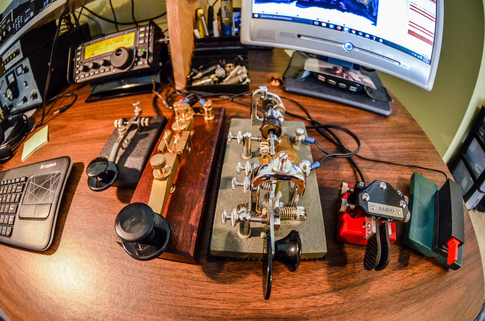
My ever changing station configuration
Left to right - Elecraft KX3, Ten-Tec Century/21 with Ten-Tec Eagle on top, the MFJ 493 keyer on the right
4 keys - Navy Flameproof, Kent Hand Key, Vibroplex Bug, N3ZN QRP paddle
The Elecraft AF1 audio filter is sitting unused in front of the Century/21
After starting our QSO the ARRL QST program started right on top of us causing QRM that forced us to move to another frequency
My old Ten-Tec Century/21 is a lot of fun to use and its direct conversion receiver makes CW sound beautiful. But the frequency dial is fairly imprecise so when I asked the station to QSY up 1kHz finding him again was a bit of a challenge. When I heard him I had to zero-beat him again to make sure I was on the correct side of the direct conversion receivers passband.
Enjoy the QSO and the QRM dodging...
Shooting this video
This video was a bit harder to shoot than what I normally do. I usually place my camera to one side but I wanted to use my fisheye lens and shoot the QSO from above.
While shooting I was straddling the tripod with the camera right in front of my face so I was reaching around the tripod to use my keys and get to my keyboard for logging. It was a bit awkward, and in the video you'll see me bump the VFO while trying to operate the radio because I couldn't really see what I was doing. It's always fun to add a level of difficulty while making these videos.
Coming back to the hobby in 2015 I re-entered as a CW / QRP operator and I searched for a good QRP radio. The Elecraft KX3 certainly qualified and it has been a great radio to use, especially when portable.
Elecraft KX3 -- stellar radio for portable QRP operations
But a few months after getting my KX3 an old TenTec Century/21 found it's way onto my desk and through numerous blog entries you may note that for some reason I kept gravitating to use it rather than my KX3 when I operated from the shack, even though the KX3 beats the old C21 technically in absolutely EVERY regard. I just enjoyed operating CW with the old radio more than the KX3. I couldn't explain why.
Fast forward to late March of 2016. I purchased a used TenTec Eagle from my friend AA4XX and began using it as my primary radio when I wasn't portable. Here again the KX3 trumps the Eagle in nearly every technical aspect and offers dozens more features. I just kept gravitating to use the TenTec radios rather than the Elecraft.
I used the my KX3 for Field Day in 2016 and after I packed up and brought it home the KX3 stayed in my backpack and only came out for portable outings. It did not go back on my desk. The KX3 cried little electronic tears while the Eagle gloated...
Ten-Tec Eagle -- compact / simple HF transceiver
Why no love for the KX3?
Time passed, and over the new year break I got to thinking about what I missed about having my KX3 on the desk; like its RX/IQ output for HDSDR and the ease working DX splits using it's dual watch capability and it's integration to logging applications like the ability to trigger CW macros from my logging software. The list of "nice-stuff" goes on and on since the KX3 contains multiple kitchen sinks... So I re-organized my desk to make room for the KX3 again and operated with it exclusively over the past few days...
I was getting ear fatigue and my ears rang in the evenings. This was not the sort of ringing in the New Year that I wanted. I had been previously operating the same amount with the Eagle over the past month without the earaches. Something was amiss.
Had I finally discovered why I keep going back to my TenTec radios?
Audio, Audio, Audio
So over time, even when I switched back and forth between radios there was a subtle "ouch" occurring when I used the KX3. I enjoy CW and digging out weak signals can be fun... or it can be painful. I guess when I sat down to use a radio and my hand hovered between the "Oh-so-feature-rich" KX3 and the "Nice-personality" Eagle my brain was saying "choose the nice personality" you're happier that way.
But there was a underlying reality to the choice I was making.
Just the facts mam
I used an audio frequency analyzer to capture audio from each radio by sandwiching the microphone in my headphones. It hears what I would hear. And the graphs tell a tale.
Below is one graph for each radio. The RED graph line in each chart is the averaged "peaked" frequency output audio during the same QSO. Ignore the green line as it was just the instantaneous audio at the time I froze the display between takes. The CW sidetone on each radio is set to 620Hz.
I re-ran this capture for each radio a few times during a lengthy ragchew between two stations. The signal strength was around S5-S7. It wasn't a strong signal which is typical of what I work, especially as the Solar cycle winds down.
I tried the captures with and without noise reduction on each radio. The RF was rolled off as evenly as I could determine for each and both were set to a DSP filter bandwidth of approximately 400Hz. Both radios were using the same antenna and everything was as similar as I make it. RCVR EQ was set flat for the KX3.
Elecraft KX3 CW audio (ignore green graph line)
Ten-Tec Eagle CW audio (ignore green graph line)
The CW audio output from each of the two radios is distinctive
KX3 audio demonstrates
shoulder noise
Eagle has clean audio
There's clearly a CW signal peak around 620Hz in each radio but the KX3 shows a significant shoulder of audio just 9dB down from the peak below the center frequency
Whereas the Eagle has a clear peak presenting a narrow tone range at the sidetone pitch with narrow shoulders down to the filter width.
Confirmation of my subjective tests
When I saw this I literally said "Aha!"
This confirmed what my ears and my subconcious had been telling me. The KX3 is more fatiguing to listen to than the Eagle because it presents more noise in the audio or at least a wider audio signal given the same DSP filter setting. I've always remarked about my TenTec radios that their CW seemed to float above the noise. I believe it's related to the cleaner audio filtering. The TenTec Eagle just has cleaner audio out of the box. It has no audio adjustments beyond AF and NR, no menus for fine tuning. My old TenTec Century/21 sounds the same when using its 500Hz selectivity setting.
In my opinion Ten-Tec just got CW right.
Yes, I have tried using the KX3 RCVR EQ settings to reduce that lower frequency noise and the problem IMO is that the EQ is more for SSB audio. I think the Q for each setting is too broad and when I try to reduce the low frequency noise IMO it just makes the audio sound mushy. I just can't get as "clean" sounding CW tone out of the Elecraft as I can the Ten-Tec.
OK, "sound" is a subjective thing. No two people will hear the same thing the same way and frequencies that bother me may not bother you, but it seems pretty clear from the graphs that the CW audio from the KX3 doesn't match the Eagle.
Summary
Admittedly, my test involved a very small sample size of one radio from each manufacturer. It's just that I'd put the KX3 back on the desk after a many month absence and my ringing ears got me to investigate the cause a bit more scientifically.
I will continue to use the KX3 for portable ops because it is a great self-contained radio and when I work portable I usually operate for much shorter periods so the audio doesn't become an issue.
Man, I hope Ten-Tec can come back from the grave. They sure made some fine radios for CW operators.
Keys left to right Nye Viking, Kent Hand key, Vibroplex Original Bug, N3ZN ZN-QRP paddle, Palm Single paddle
My collection of keys has grown over the past few months and I find that I like each for their particular qualities.
Keys from left to right
The Nye Viking is somewhere between a traditional J-38 low style American key and a tall European style. At first I couldn't get any sort of coordination with it even after a couple hours of practice and it stayed in the closet for a few months. Eventually I wanted to leave a key hooked up to the old Century/21 so I didn't have to move the output of my external keyer so the Viking came back out. I've finally become accustomed to it and am even beginning to enjoy it as much as the Kent. I'm amazed at how different two straight keys can be.
The Kent Hand key continues to be my favorite key for straight key operation. The Kent is operated using your entire arm off the desk and when I send using it above 15wpm I get the entire desk shaking with the motion. My desk light starts casting dancing shadows across the equipment from the vibration and with the clacking of the key and the blare of the sidetone the world of CW becomes visceral.
The Vibroplex Bug remains at the center of the collection because I have some strange affinity for the quirky bug. I use it on every QSO where I hear another bug operator or with SKCC operators that are sending faster than 17wpm. It has a non-cosmetic, yet effective, weight added from an old steel spacer to slow it down to a range of 21wpm to 16wpm and some dental floss around the DIT contact spring to reduce the potential bounce which results in scratchy sounding DITS.
The N3ZN ZN-QRP paddle is a work of art and when I'm working higher speed CW it's my go-to key. The carbon fiber finger pieces and lightweight clickety action always puts a smile on my face. I keep it connected to the external Ham Keyer which has a handy knob to for quickly adjusting keyer speed.
The Palm Single to the right is magnetically mounted to a steel base a friend made for me. I pull it off the base when I go portable as it's my go-to key for all my portable operations. But when I'm at the home station I leave it hooked up to the keyer input on the Ten-Tec Eagle because the Eagle's keyer is only Iambic-B mode and I just can't get used to "B-Mode". Using a single, non-iambic paddle eliminates the weird timing of the B iambic mode. I really should learn mode-B since it seems to be standard on Ten-Tec and Kenwood radios.
The 3 stars in the center are the Kent Hand key, Vibroplex Original Bug and the N3ZN paddle
The 3 keys in the middle (Kent Hand key, Vibroplex Bug and N3ZN paddle) remain hooked up to the Ham Keyer and I move the output of that keyer to whichever rig I'm primarily using at the time. That keyer uses Iambic-Mode-A which I'm comfortable with and it debounces the scratchiness of the Bug. I hook the output of the keyer up to either the PTT line on the Eagle or the secondary key input on the KX3. When using the C21 I just use the Nye straight key.
Debouncing a Vibroplex Bug
Side story on the Bug... If you get a Vibroplex bug and hook it up to the PTT line of your radio you may find that you're missing DITS or that the output sounds broken or scratchy. The PTT line of many radios is not "buffered" meaning it is reacting to every contact closure. On a bug, the DIT contact is actually bouncing potentially hundreds of times a second since the contact force is so light and doesn't make a clean closure. Many keyers will filter out those multiple contacts or bounces. My old HAM KEYER weight control actually serves as a DIT weight control for the manual keys as well so it's ideal for use with the bug.
KE6EE offered me this nice explanation of what was going on:
The more usual term for the process of dealing with problems of contact closure is "debouncing." Google and you will find lots of interesting visuals and explanations.
The actual start and finish of contact closures and openings in switches, relays and keys, is not a simple off-and-on process but a series of "bounces." Dit contact closures on a bug are likely to be very bouncy.
Bug dit contact design and bug maintenance and adjustment are critical for minimizing bounce. Ops with Vibroplex-style dit contacts often put a piece of rubber or plastic foam in the U-shaped dit contact spring. The Begali bug uses a unique pointed and spring-loaded dit contact. Many bug ops, from my observations on the air, do not adjust their dit weight properly to minimize a scratchy sound.
Transmitter keying circuits are usually "debounced" in various ways, the simplest perhaps being to put a capacitor across the key contact circuit. A PTT circuit doesn't need to be debounced so it isn't. Keyers often have debounce circuits designed to be used with straight keys and bugs.
Try different keys
So if you are getting into CW try some different keys. I think you'll be surprised by the differences and find that your mood or situation will dictate the use of one key over another. Morse keys on the used market aren't expensive if you shop carefully so you can build quite a collection. They also tend to hold their value if you find that you've obtained a key or two that you just can't grok.
My ever changing station sporting a spiffy new chair
That's all for now
So lower your power and raise your expectations
73
Richard, AA4OO
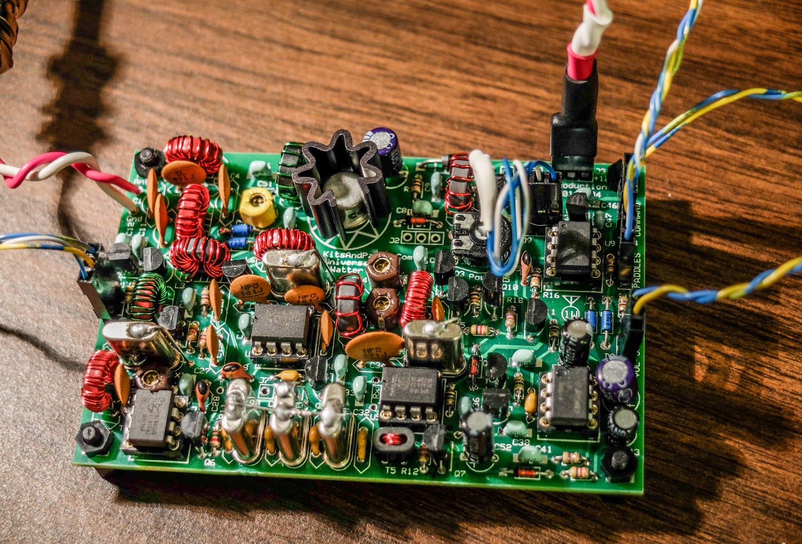
The Universal 1Watter (also called the 1H2O) is a full featured little superhet radio transceiver that you can build for about $50. It doesn't come with an enclosure, a tuning pot, speed pot or an on/off switch so that will cost extra unless you already have some in the junk bin.
Some of the features include;
1 mighty watt of output
Good selectivity from the 3 crystal filters
A VCXO tuned frequency range for the 40m band from approximately 7,020 kHz through 7,039 kHz
A built-in full functioned keyer with provision for adding a speed pot and messages
Included command button accesses the functions of the electronic keyer
Natural sounding sidetone (nicer than my Ten-Tec Century/21)
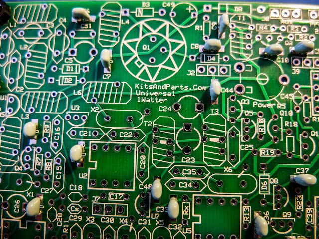
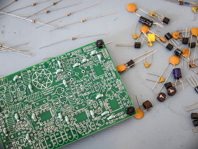
The Build
The kit is delivered in a box and inside are a couple of brown paper bags stapled together. Inside one of the bags are a couple of plastic bags with the components. The other bag contained the header kit. The ferrite toroid mix types are separated in different unmarked plastic bags so don't mix them up (the instructions tell you which bag has each mix). If anything is missing the kit supplier (Diz, W8DIZ) is very responsive.
The kit includes both SMT caps and through hole caps. I tried to solder one of the SMTs but I didn't have the right kind of tweezers to hold it in position for soldering so I used the through hole caps.
SMT and through hole caps are supplied
This is the 3rd revision of the Universal 1Watter board and I was the first to build the 40m version.
While the schematic was correct, some of the instructions weren't sorted out properly for the 40m kit. I related issues as I found them to the designer and he promptly updated the online documentation.
I soldered the components and wound toroids as I had time over a few evenings and the initial voltage tests went well.
using through hole capacitors rather than the SMTs
some of the bits and bobs
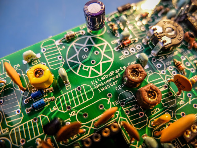
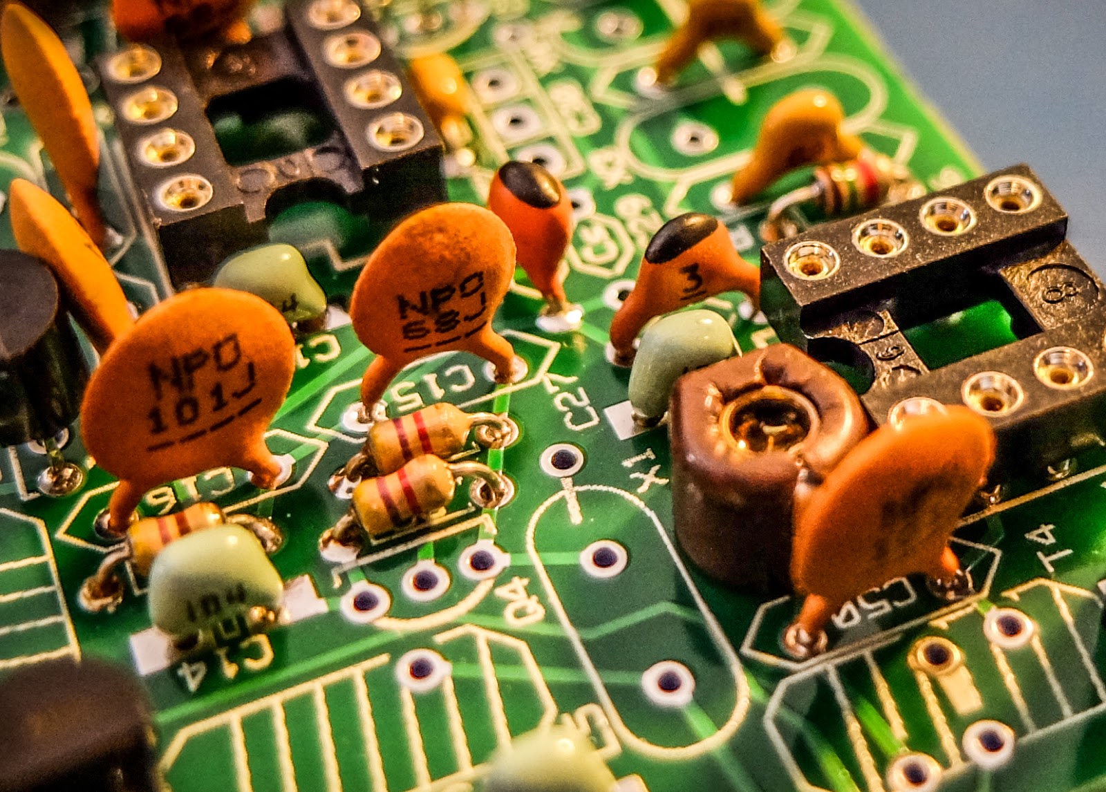
build is progressing
close up
XTAL filters give it good selectivity
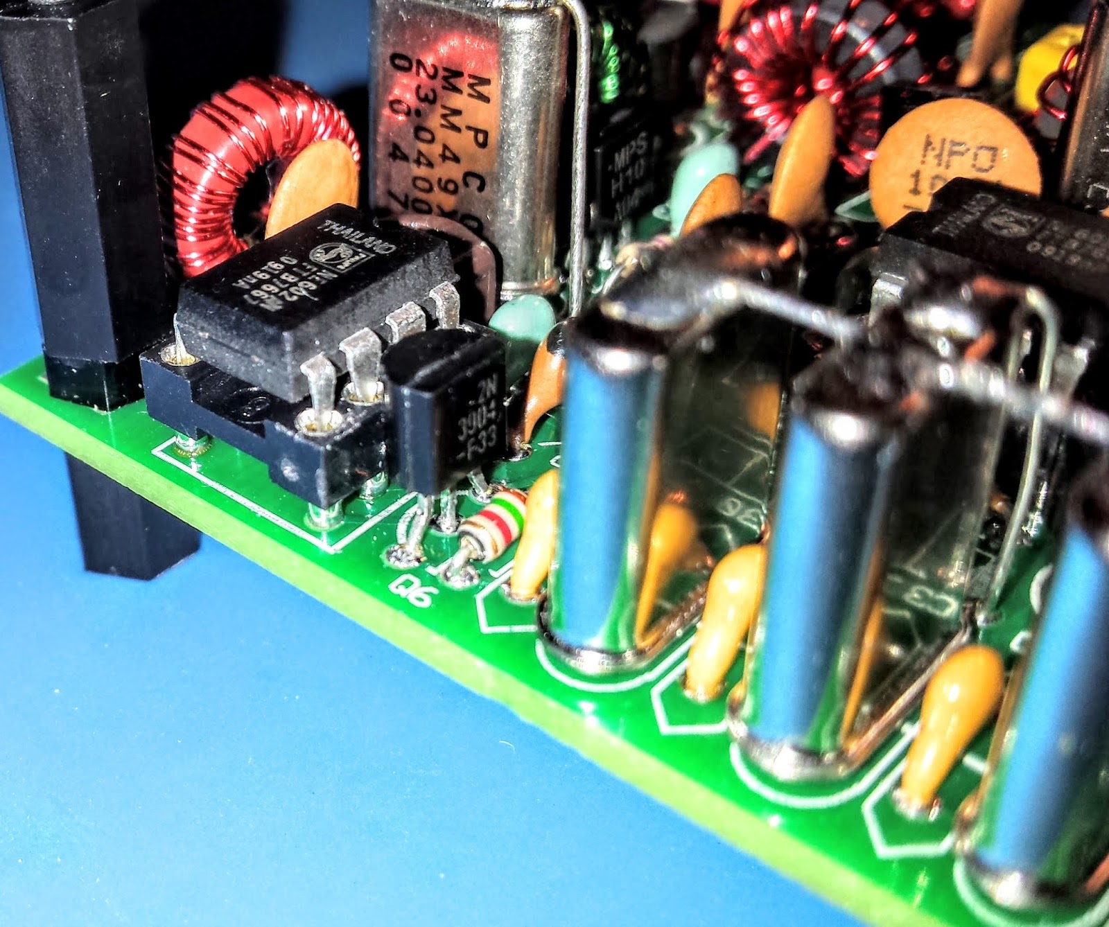
Everything except the final transistor
AGC circuit
Debugging
When the build was completed I connected the rig to an antenna and heard nothing.
The keying circuit and transmitter worked fine and I verified those functions but the receiver was deaf as a stump.
Thus began a number of days of investigation. Diz (the creator of the board) guided me through a number of debugging steps.
The first recommendation was to examine and rewind the binocular toroid balun that transformed the impedance from the xtal filters to the input of the U5 oscillator. He believed that I may had wound it incorrectly. I desoldered it and rewound it but that did not resolve the issue.
He then guided me through determining if one of the filter crystals or filter capacitors was bad. I desoldered a few components as a tests but that did not resolve the issue.
There are 3 identical mixer chips on the board. I swapped them around as there was a suggestion that there were some faulty chips in one of Diz's shipments.
I then took the board to my Elmer Paul Stroud AA4XX. He had a signal generator, Oscilloscope and RF detector. He traced the RF and all looked well but we still were unable to obtain any signal through the U5 mixer. Lastly we tried disconnecting the AGC transistor to see if it was clamping it and that didn't resolve it either.
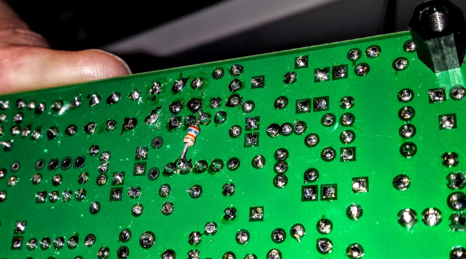
Diz asked me to return the radio to him so he could take a look. After a couple weeks he emailed me saying he thought the BFO xtal might have a problem. But he later discovered that the oscillator in U5 was not starting up. Apparently the circuit design had a low Q and needed more current to get the oscillator working. He modified the design, adding a 16k resistor to the bottom of the board on U5 to get the oscillator going. After that all was well and he shipped the board back to me.
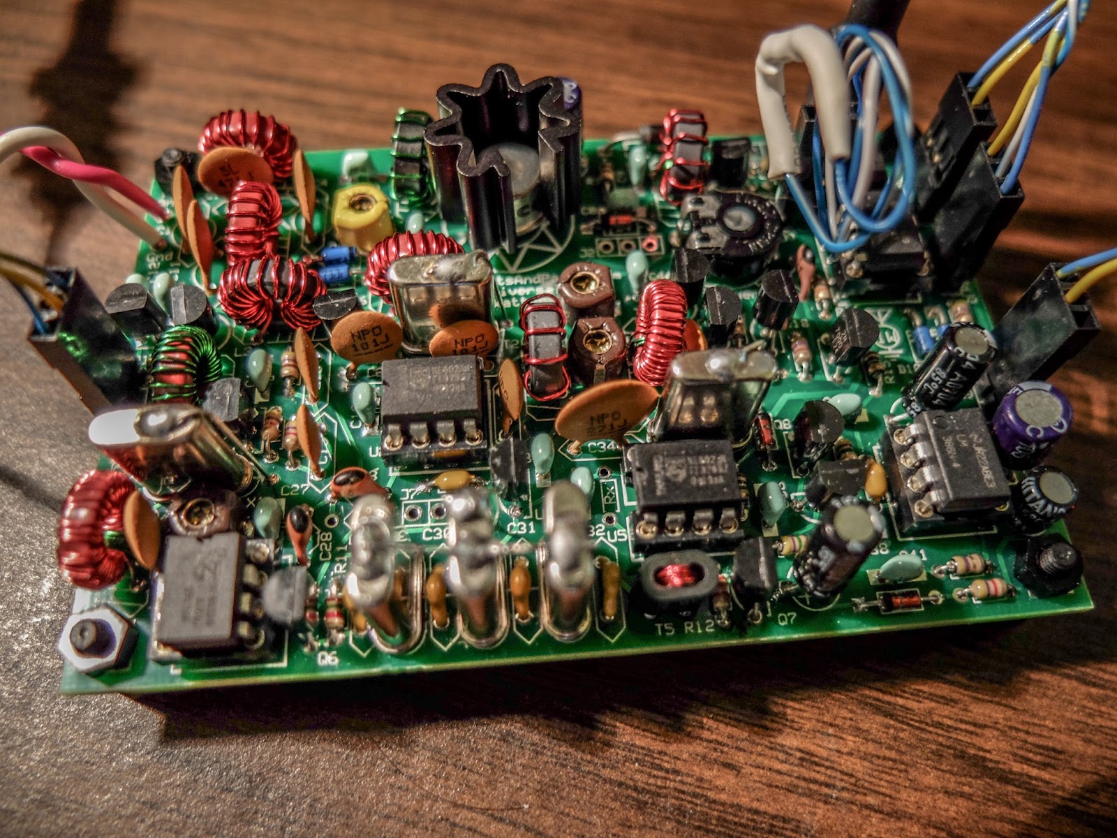
The FIX for all those problems required an extra resistor connected across U5
Learning from problems
Being the first person to build a particular version of a kit brings its own set of challenges, especially when you're as new to kit building debugging RF problems as I am. However I'm actually glad the kit didn't work right at the initial build. The process of debugging the board, was a great learning process. I studied the schematics and learned, as best I could, the function of each circuit so that I could better understand how to test it. During the debugging process Diz instructed me that although RF signal generators and scopes are useful you can tell a lot by touching a RF component with an inductive metal object and listening for a buzz or hum from the BFO. So all-in-all, even though the bug in the board was not due to a error on my part, I'm glad it occurred. I understand more about superhet radio design than I did before and more than if the kit had worked right off the bat.
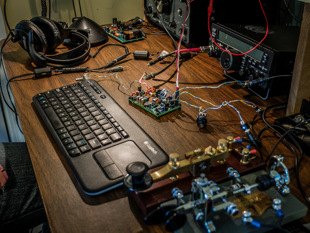
On the air
After receiving the board back, I hooked up the frequency XCO potentiometer, paddle, command button, audio and output potentiometer and an external speaker. I then connected a 12v battery and heard the 1H2O keyer chip announce itself at power up in Morse "1 W".
Frequency control pot on the left
Volume control, output jack, cmd pot and paddle input
You can change speeds and modify settings via the command button which I have not reviewed yet. I also plan to add the speed pot so that I can easily change keyer speed without entering the command menu. For this first on-air excursion I was using it at the default startup 15wpm keyer speed. You can default the speed higher with a different resistor value. I have a resistor shrink wrapped and connected in-line to the blue-white wire coiling above the radio connecting to the speed pot terminal. In essence fixing the speed at 15wpm until I add the speed pot.
Ready to transmit
On the air... I was using my paddle out of the photo to the right of the Bug
First On Air QSO
I tuned around and found a strong station at the end of a QSO near 7030 kHz.
When he sent the final dit-dit I called and WD4AXJ answered my first call. He was in TN near Knoxville, and I received a 559. We chatted for about 10 minutes. Sorry about the blurry video. I thought I'd focused.
After I recorded this video I found an open frequency and sent out my call. Very shortly thereafter KD2FSHanswered my call and reported me as 599!
Whoo - hoo. 599 for my little 1Watter 40m.
I was transmitting using my 40m attic antenna. So deed restricted HAMs take note. You can build a one-watt radio and make contacts using your attic antenna. Haha.
You'll hear in the video there is some weirdness going on with the audio derived AGC. It is clamping down sometimes and is worse when I don't have the volume turned up very loud. When I began calling it clamped after every semi-break-in but didn't do it much after that. I'll have to look into that.
The AGC clamping may be a side effect of the increased gain Diz added to the BFO oscillator. I'll ask the forum.
Other than the AGC issue I'm super pleased with the little board. I touched the heat sync a couple of times after transmitting my side of the qso and it was warm but not really hot. It seems as though as long as you have a reasonable match to the antenna the power transistor should be happy.
My next steps are to get it in an enclosure and get it out to the Excalibur antenna site to hook onto that nice 40m doublet we put up a couple weekends ago. I plan to use my efficient little BLT tuner for that purpose. I will do a further review of the feature set on the keyer and record some more qsos for a later review.
Summary
The band was fairly busy and the little 1Watter did a fine job with stations on nearby frequencies. You can hear some getting around the passband but it is not bad at all. I'll do some tests to further define it's selectivity but at first glance it is far better than my old Ten-Tec Century/21.
My calls were answered quickly and I received good signal reports. It didn't sound as though the transmitter was drifting at all during the QSO. That's one advantage of using VCXO in the design. The disadvantage of using a crystal controlled oscillator for the frequency control is limited tuning range. The transmitter only has about a 18 kHz tuning range around 7030 kHz and I don't find many of the SKCC folks around that frequency but it is the QRP watering hole for 40m.
It is possible to shift the frequency with some capacitance changes but I think I'll leave it as is for a time and see how many states I can work.
Just imagine. This little $50 single band kit has good selectivity, a nice built-in keyer with a natural sounding sidetone, and lest we forget... You get a MIGHTY 1 WATT of OUTPUT. What more could a QRP ham need.
That one-watt of output was sufficient for all the QSOs I attempted tonight.
So lower your power and raise your expectations
72/73
Richard, AA4OO
UPDATE: 04/01/2016
I
am still having the AGC pumping issue and others on the list have
reported similar issues but only on receive. It happens to me when I
key unless I turn up the volume very high. I did get it installed in a
case but I still need to wire up a real power connector rather than
using alligator clips.
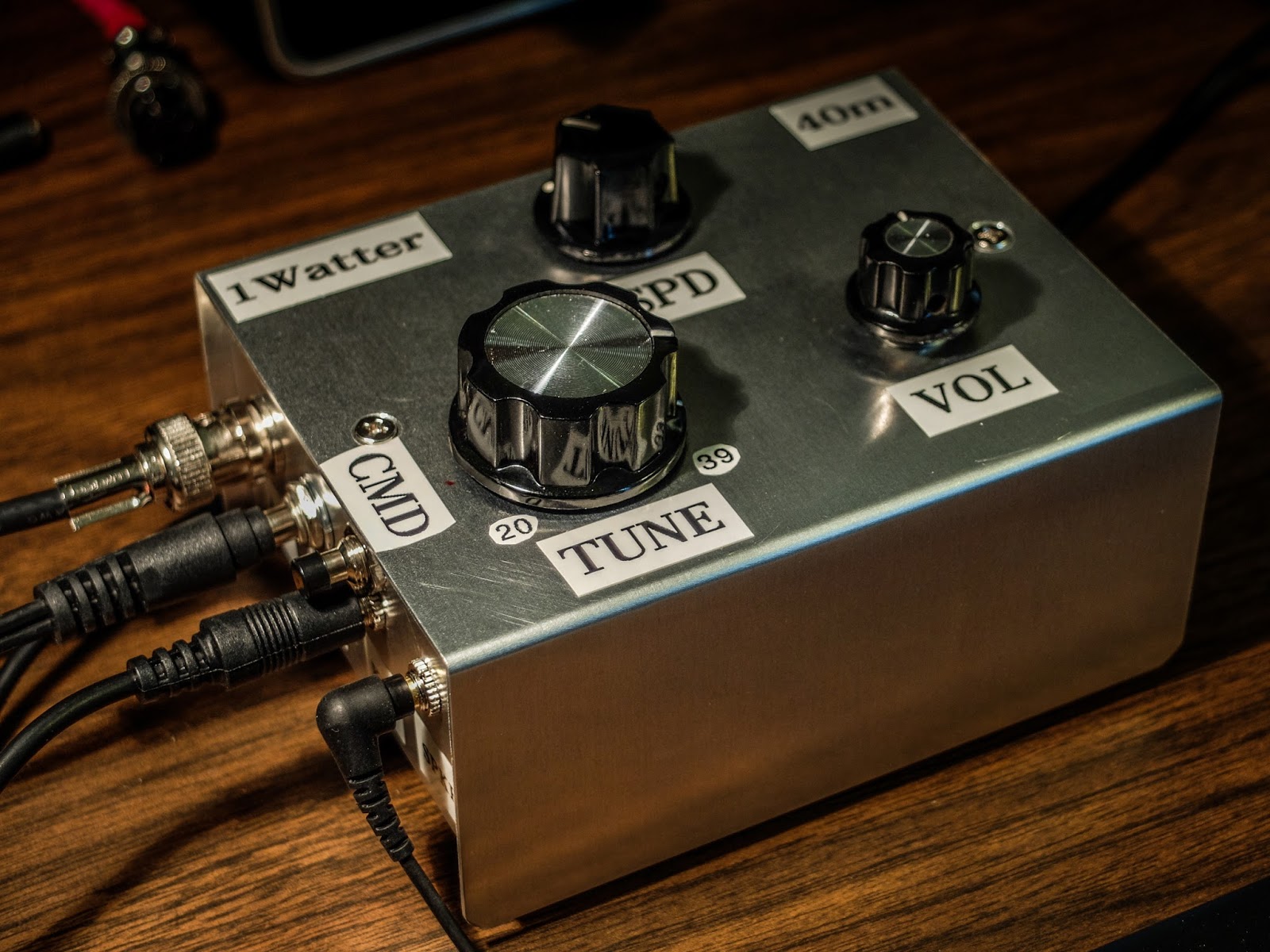
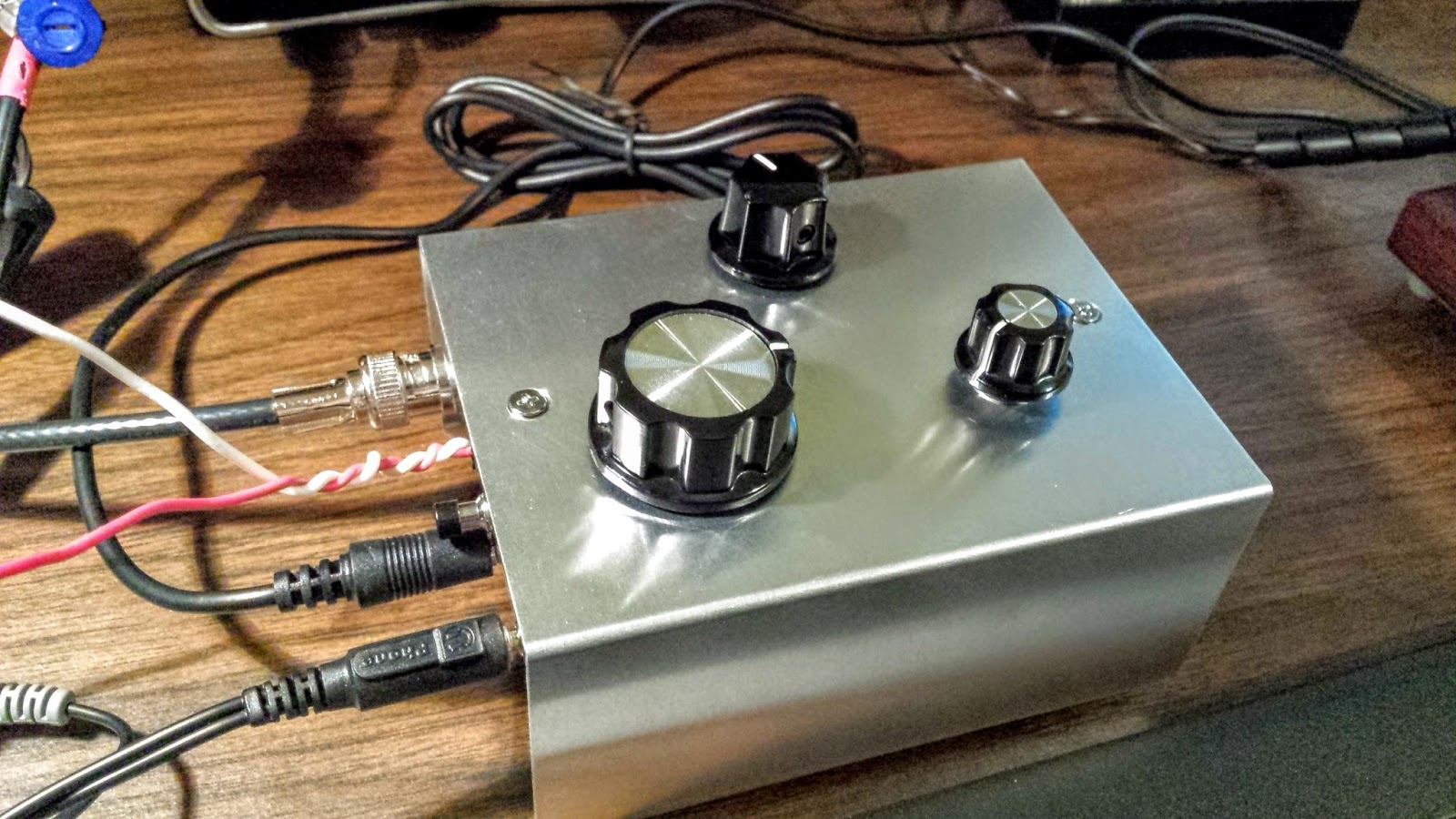
!Watter installed in a case
UPDATE: 04/05/2016
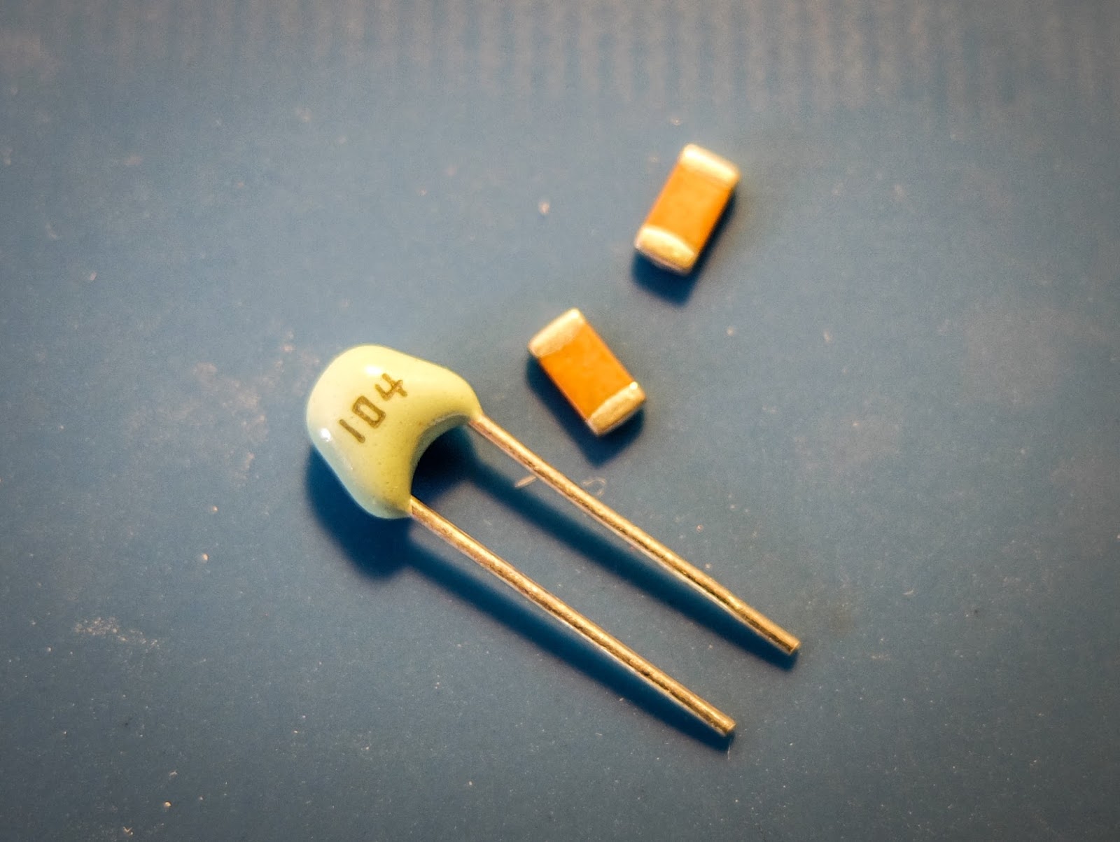
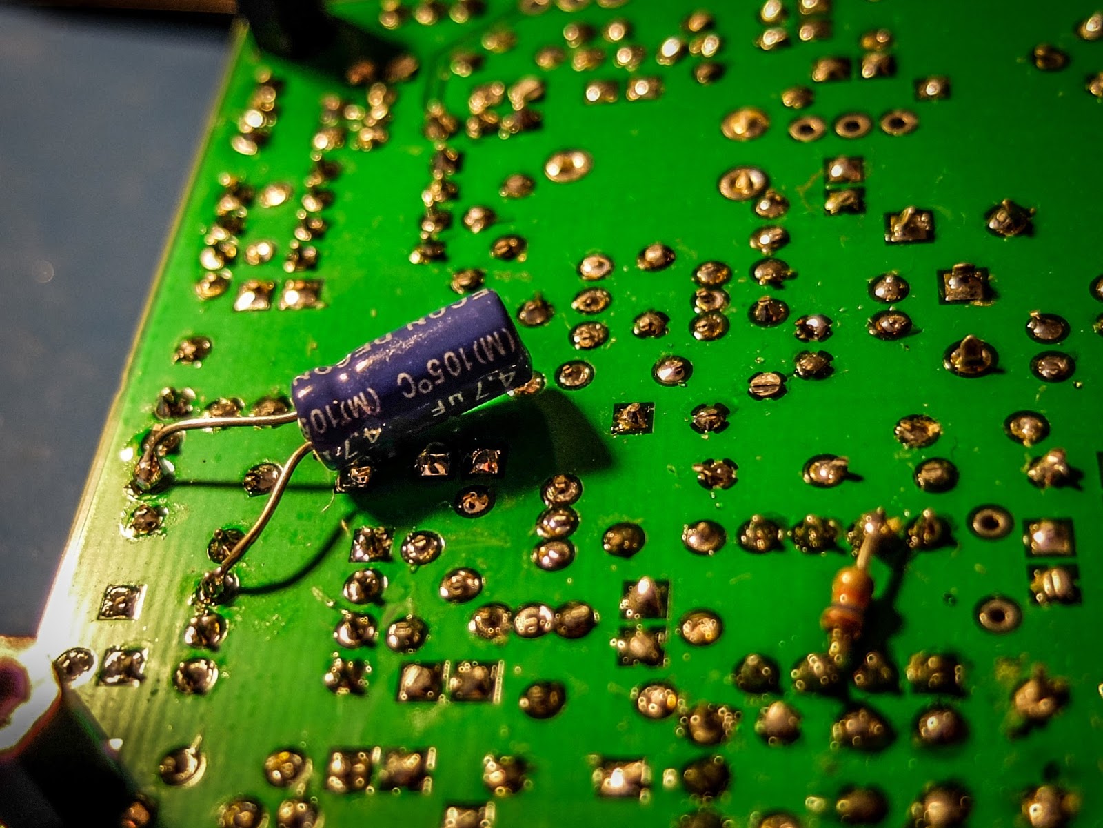
After doing quite a bit of reading I learned that the LM386 op-amp used in the 1watter
is rather notorious for audio oscillations. There are a number of
suggested fixes. I went with a 4.7uf cap connecting Pin 7 on U6 (the
LM386) to ground. That hasn't totally resolved the issue but it's much
less pronounced now.
cap fix for LM386 oscillations
I
have it in the case with all the proper plugs now (see below) so I'm
happy. I've been making QSOs every day with it and it continues to
amaze me and the stations that work me. It is stable as a rock with
regard to frequency and the large knob with the single turn 10k pot
seems to work well for tuning. I have enough control to vary the
frequency slightly without having to turn it too much. The tuning range
is only about 20kHz so just 3 frequency markers are plenty to let me
know what frequency I'm near. The selectivity is just fantastic for
such a simple little radio. Diz has created an inexpensive winner.
1Watter in enclosure with all the proper connectors for the case Information on case and knobs: