Showing posts sorted by relevance for query century/21. Sort by date Show all posts

Tuesday, March 29, 2016

It's ALIVE !

The 1Watter 40m #551 -- Lives

The 1Watter 40m on it's inaugural QSO
Inside the enclosure

The 1Watter is a kit from kits and parts dot com 

The Universal 1Watter (also called the 1H2O) is a full featured little superhet radio transceiver that you can build for about $50.  It doesn't come with an enclosure, a tuning pot, speed pot or an on/off switch so that will cost extra unless you already have some in the junk bin.

Some of the features include; 
  • 1 mighty watt of output
  • Good selectivity from the 3 crystal filters
  • A VCXO tuned frequency range for the 40m band from approximately 7,020 kHz through 7,039 kHz
  • A built-in full functioned keyer with provision for adding a speed pot and messages
    • Included command button accesses the functions of the electronic keyer
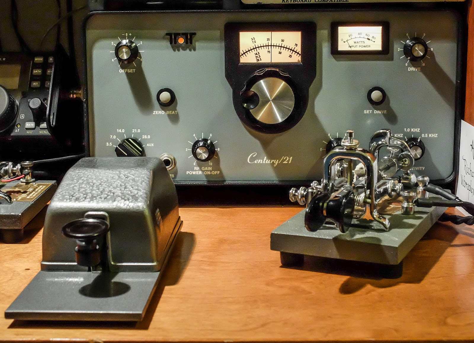
    • Natural sounding sidetone (nicer than my Ten-Tec Century/21)

The Build

The kit is delivered in a box and inside are a couple of brown paper bags stapled together.  Inside one of the bags are a couple of plastic bags with the components.  The other bag contained the header kit.  The ferrite toroid mix types are separated in different unmarked plastic bags so don't mix them up (the instructions tell you which bag has each mix).  If anything is missing the kit supplier (Diz, W8DIZ) is very responsive.  

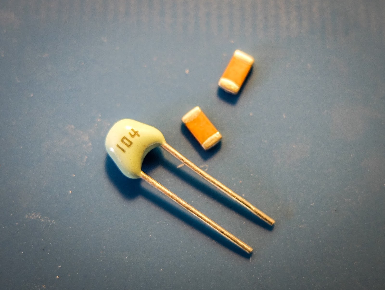
The kit includes both SMT caps and through hole caps.  I tried to solder one of the SMTs but I didn't have the right kind of tweezers to hold it in position for soldering so I used the through hole caps.

SMT and through hole caps are supplied

This is the 3rd revision of the Universal 1Watter board and I was the first to build the 40m version.  

While the schematic was correct, some of the instructions weren't sorted out properly for the 40m kit.  I related issues as I found them to the designer and he promptly updated the online documentation.

I soldered the components and wound toroids as I had time over a few evenings and the initial voltage tests went well.

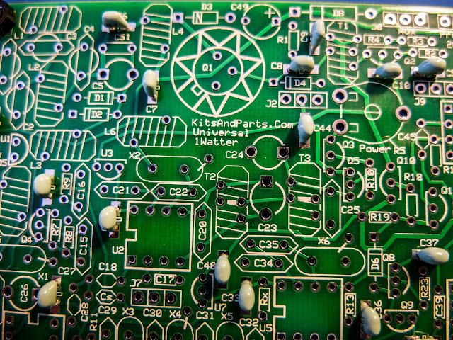
using through hole capacitors rather than the SMTs
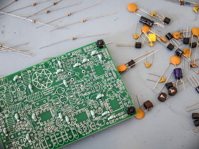
some of the bits and bobs
build is progressing
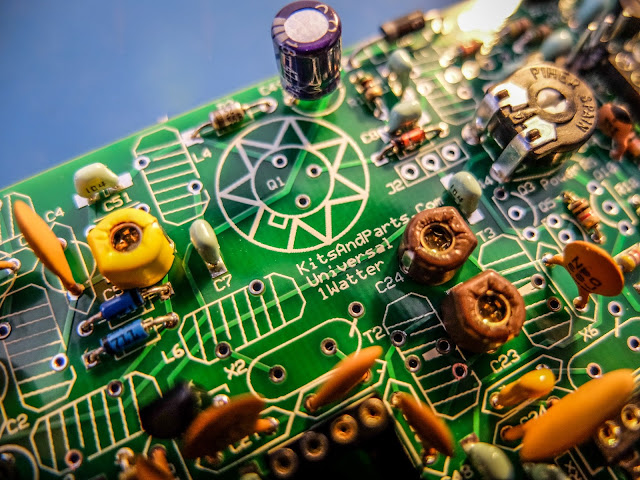
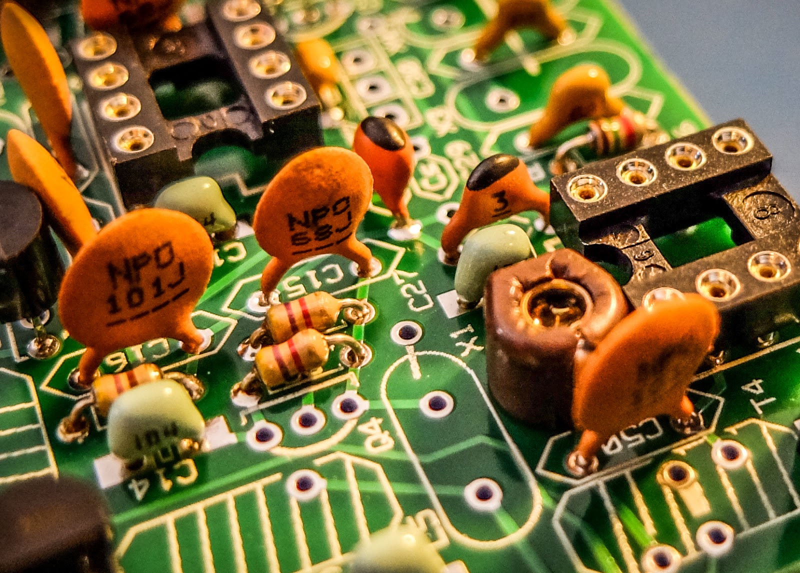
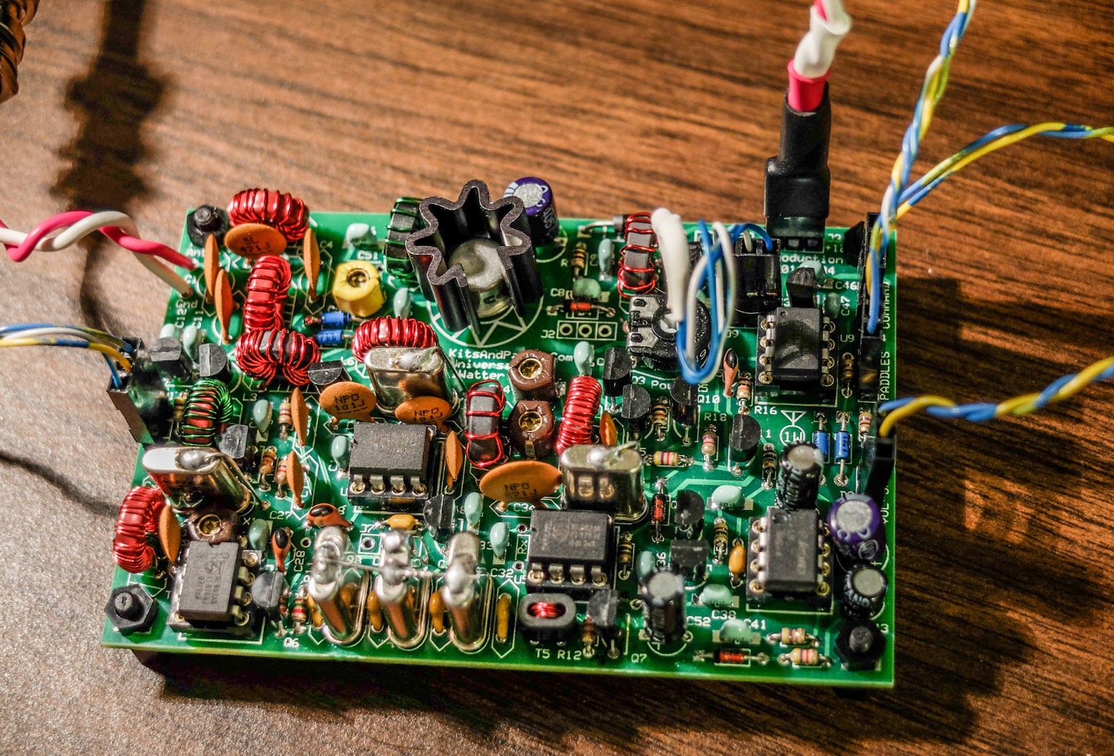
close up
XTAL filters give it good selectivity
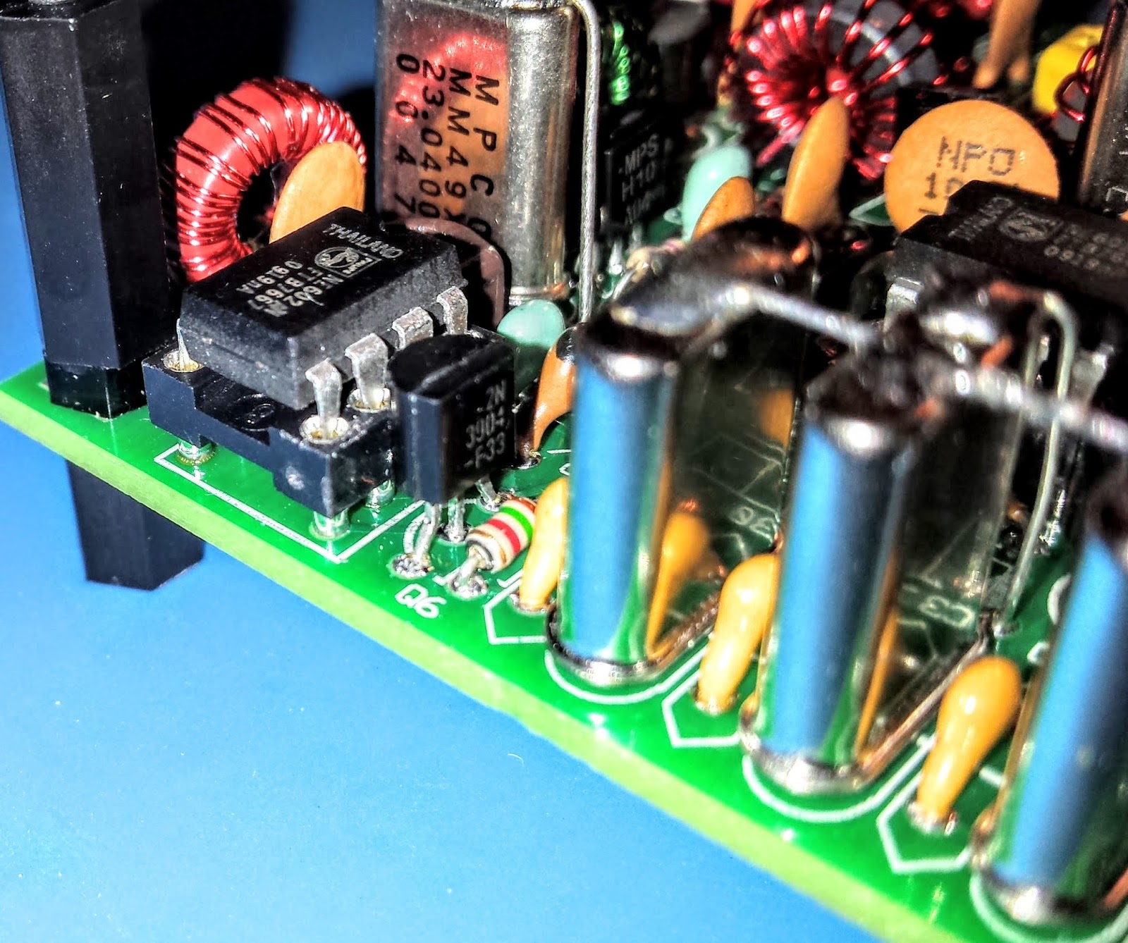
Everything except the final transistor
AGC circuit

Debugging

When the build was completed I connected the rig to an antenna and heard nothing.

The keying circuit and transmitter worked fine and I verified those functions but the receiver was deaf as a stump.

Thus began a number of days of investigation.  Diz (the creator of the board) guided me through a number of debugging steps.  

The first recommendation was to examine and rewind the binocular toroid balun that transformed the impedance from the xtal filters to the input of the U5 oscillator.  He believed that I may had wound it incorrectly.  I desoldered it and rewound it but that did not resolve the issue.

He then guided me through determining if one of the filter crystals or filter capacitors was bad.  I desoldered a few components as a tests but that did not resolve the issue.

There are 3 identical mixer chips on the board.  I swapped them around as there was a suggestion that there were some faulty chips in one of Diz's shipments.

I then took the board to my Elmer Paul Stroud AA4XX.  He had a signal generator, Oscilloscope and RF detector.  He traced the RF and all looked well but we still were unable to obtain any signal through the U5 mixer.  Lastly we tried disconnecting the AGC transistor to see if it was clamping it and that didn't resolve it either.

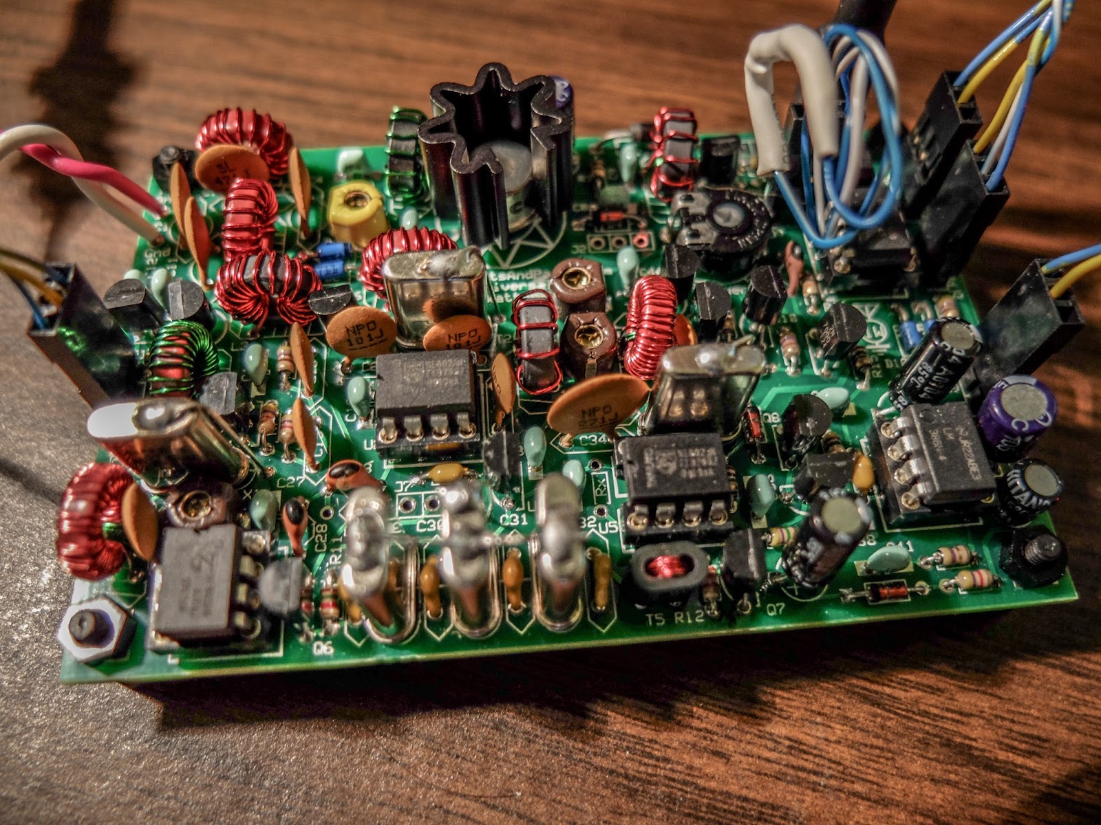
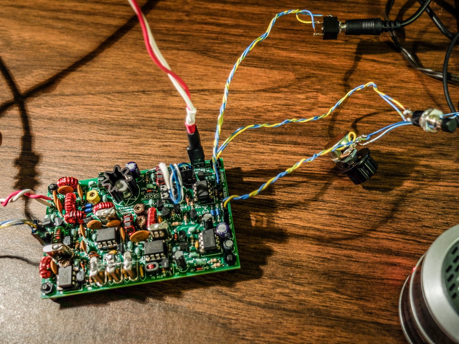
Diz asked me to return the radio to him so he could take a look.  After a couple weeks he emailed me saying he thought the BFO xtal might have a problem.  But he later discovered that the oscillator in U5 was not starting up.  Apparently the circuit design had a low Q and needed more current to get the oscillator working.  He modified the design, adding a 16k resistor to the bottom of the board on U5 to get the oscillator going.  After that all was well and he shipped the board back to me.


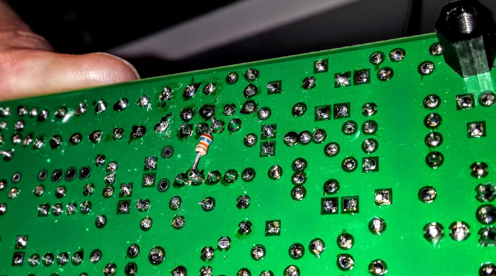
The FIX for all those problems required an extra resistor connected across U5

Learning from problems

Being the first person to build a particular version of a kit brings its own set of challenges, especially when you're as new to kit building debugging RF problems as I am.  However I'm actually glad the kit didn't work right at the initial build.

The process of debugging the board, was a great learning process.  I studied the schematics and learned, as best I could, the function of each circuit so that I could better understand how to test it.  During the debugging process Diz instructed me that although RF signal generators and scopes are useful you can tell a lot by touching a RF component with an inductive metal object and listening for a buzz or hum from the BFO.


So all-in-all, even though the bug in the board was not due to a error on my part, I'm glad it occurred.  I understand more about superhet radio design than I did before and more than if the kit had worked right off the bat.

On the air

After receiving the board back, I hooked up the frequency XCO potentiometer, paddle, command button, audio and output potentiometer and an external speaker.  I then connected a 12v battery and heard the 1H2O keyer chip announce itself at power up in Morse "1 W". 


Frequency control pot on the left
Volume control, output jack, cmd pot and paddle input
You can change speeds and modify settings via the command button which I have not reviewed yet.  I also plan to add the speed pot so that I can easily change keyer speed without entering the command menu. 

For this first on-air excursion I was using it at the default startup 15wpm keyer speed.  You can default the speed higher with a different resistor value.  


I have a resistor shrink wrapped and connected in-line to the blue-white wire coiling above the radio connecting to the speed pot terminal.  In essence fixing the speed at 15wpm until I add the speed pot.


Ready to transmit


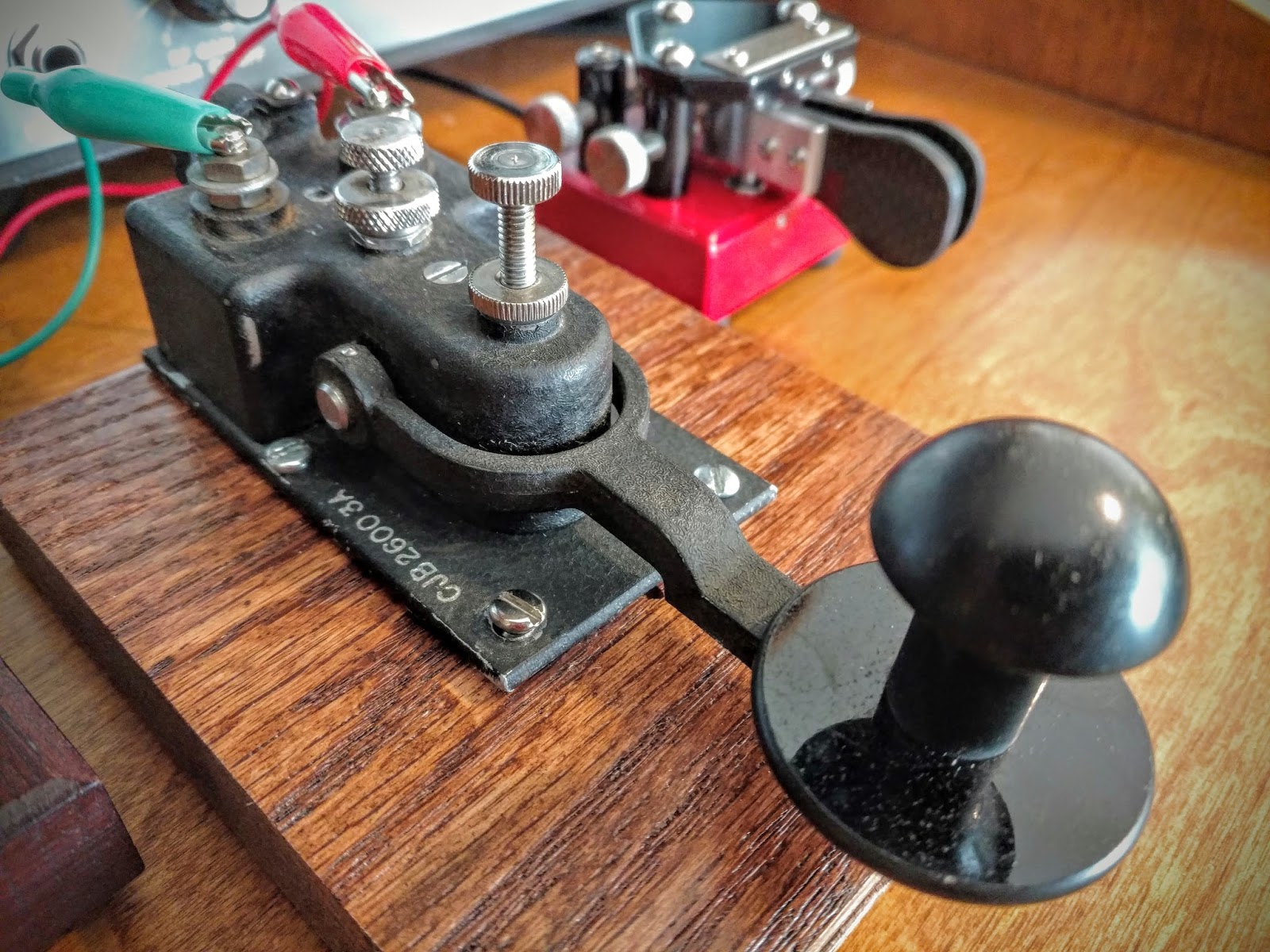
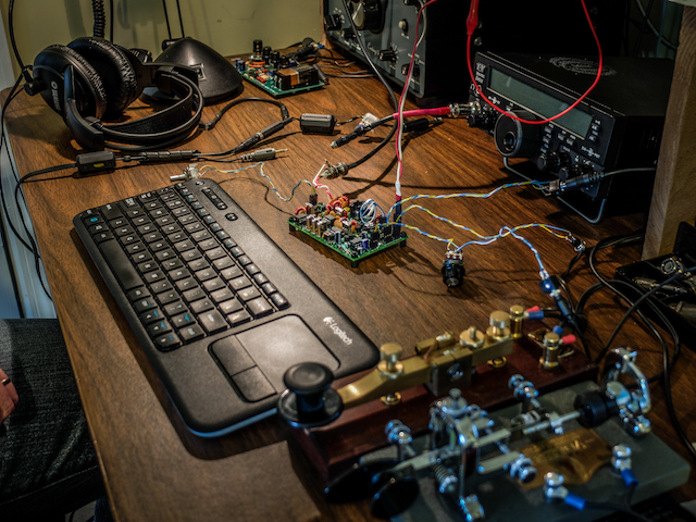
On the air... I was using my paddle out of the photo to the right of the Bug

First On Air QSO

I tuned around and found a strong station at the end of a QSO near 7030 kHz.  

When he sent the final dit-dit I called and WD4AXJ answered my first call.  He was in TN near Knoxville, and I received a 559.  We chatted for about 10 minutes. Sorry about the blurry video.  I thought I'd focused.


After I recorded this video I found an open frequency and sent out my call.  Very shortly thereafter KD2FSH answered my call and reported me as 599! 

Whoo - hoo.  599 for my little 1Watter 40m.

I was transmitting using my 40m attic antenna.  So deed restricted HAMs take note.  You can build a one-watt radio and make contacts using your attic antenna. Haha.

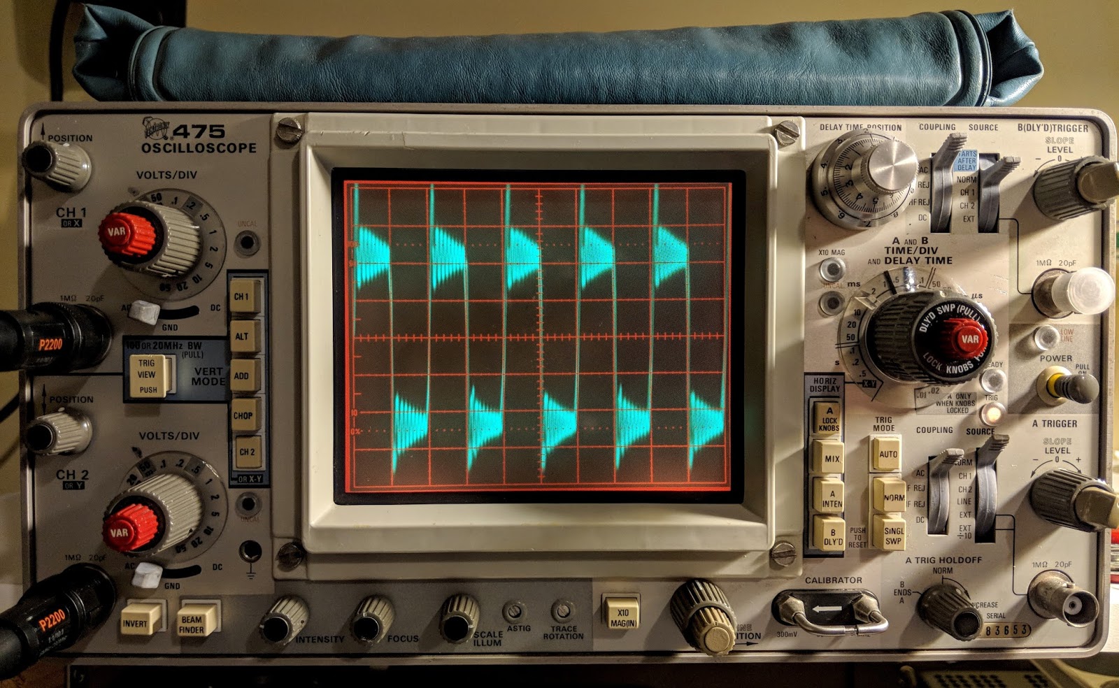
You'll hear in the video there is some weirdness going on with the audio derived AGC.  It is clamping down sometimes and is worse when I don't have the volume turned up very loud.  When I began calling it clamped after every semi-break-in but didn't do it much after that.  I'll have to look into that.

The AGC clamping may be a side effect of the increased gain Diz added to the BFO oscillator.  I'll ask the forum.  

Other than the AGC issue I'm super pleased with the little board.  I touched the heat sync a couple of times after transmitting my side of the qso and it was warm but not really hot.  It seems as though as long as you have a reasonable match to the antenna the power transistor should be happy.

My next steps are to get it in an enclosure and get it out to the Excalibur antenna site to hook onto that nice 40m doublet we put up a couple weekends ago.  I plan to use my efficient little BLT tuner for that purpose.  I will do a further review of the feature set on the keyer and record some more qsos for a later review.

Summary

The band was fairly busy and the little 1Watter did a fine job with stations on nearby frequencies. You can hear some getting around the passband but it is not bad at all.  I'll do some tests to further define it's selectivity but at first glance it is far better than my old Ten-Tec Century/21.  

My calls were answered quickly and I received good signal reports. It didn't sound as though the transmitter was drifting at all during the QSO. That's one advantage of using VCXO in the design.  The disadvantage of using a crystal controlled oscillator for the frequency control is limited tuning range.  The transmitter only has about a 18 kHz tuning range around 7030 kHz and I don't find many of the SKCC folks around that frequency but it is the QRP watering hole for 40m.

It is possible to shift the frequency with some capacitance changes but I think I'll leave it as is for a time and see how many states I can work.

Just imagine.  This little $50 single band kit has good selectivity, a nice built-in keyer with a natural sounding sidetone, and lest we forget... You get a MIGHTY 1 WATT of OUTPUT.  What more could a QRP ham need.


That one-watt of output was sufficient for all the QSOs I attempted tonight.

So lower your power and raise your expectations

72/73

Richard, AA4OO

UPDATE: 04/01/2016

I am still having the AGC pumping issue and others on the list have reported similar issues but only on receive.  It happens to me when I key unless I turn up the volume very high.  I did get it installed in a case but I still need to wire up a real power connector rather than using alligator clips.

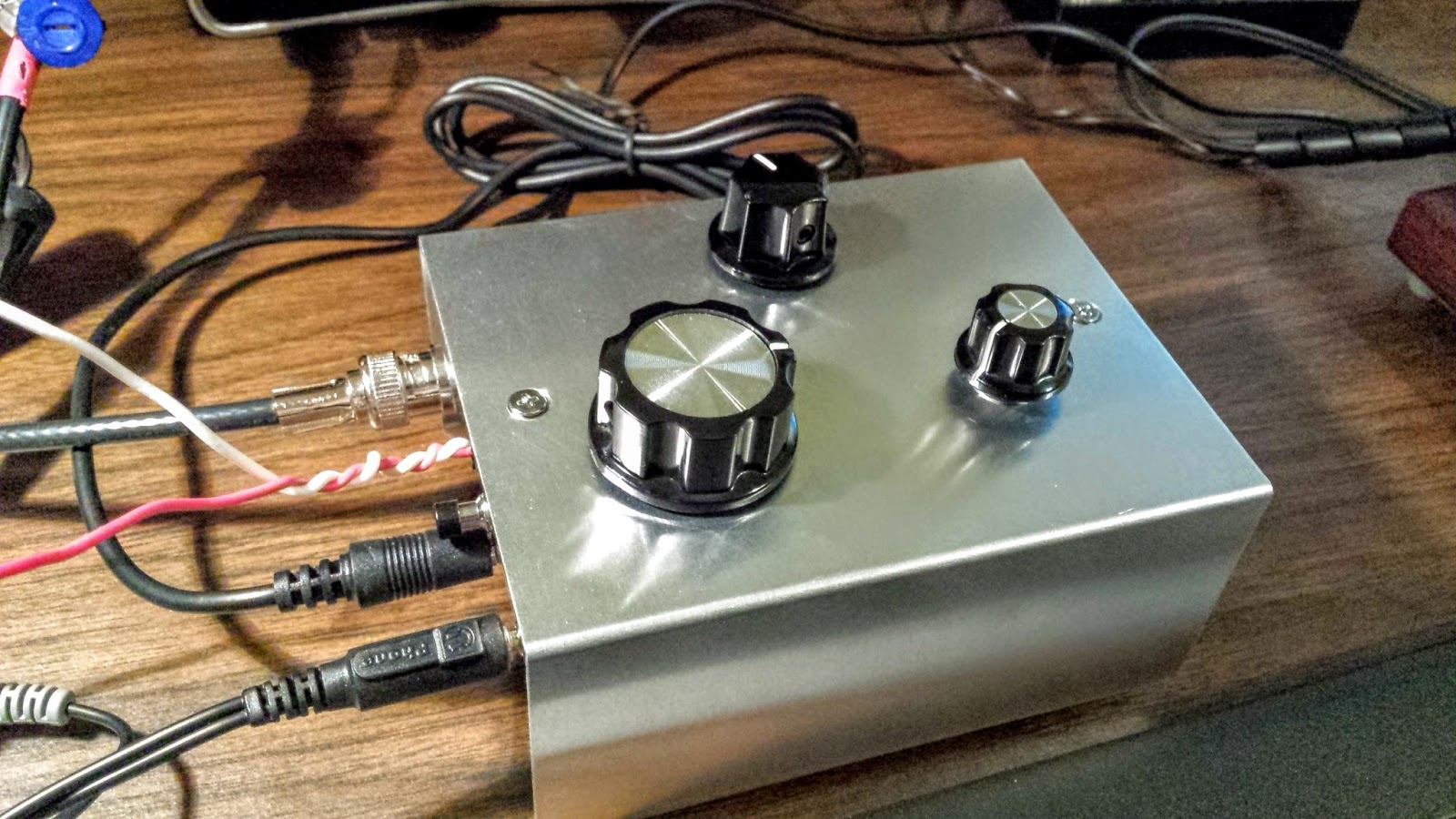
!Watter installed in a case

UPDATE: 04/05/2016

After doing quite a bit of reading I learned that the LM386 op-amp used in the 1watter is rather notorious for audio oscillations.  There are a number of suggested fixes.  I went with a 4.7uf cap connecting Pin 7 on U6 (the LM386) to ground.  That hasn't totally resolved the issue but it's much less pronounced now.  


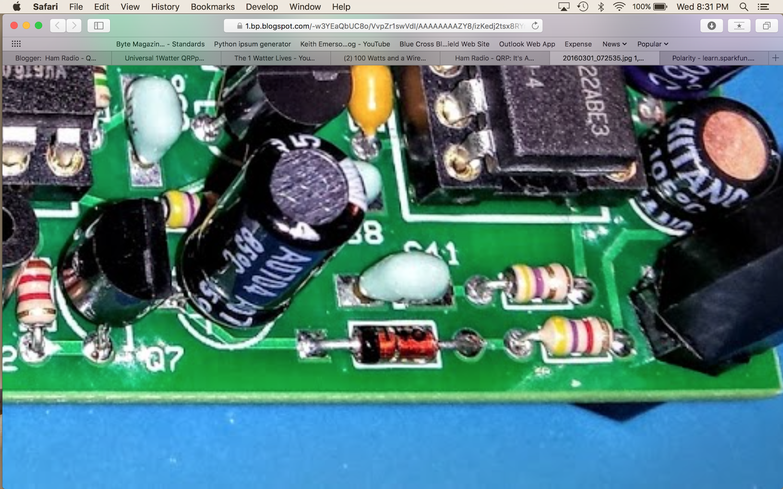
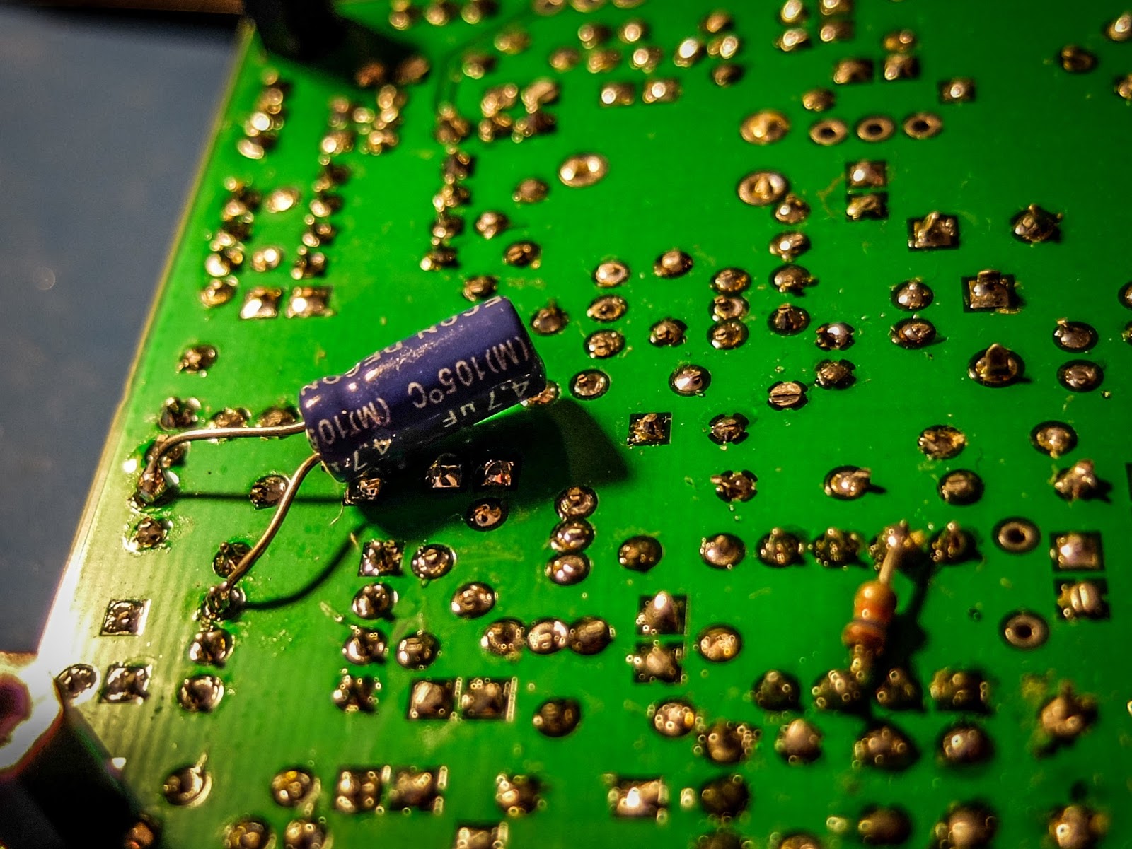
cap fix for LM386 oscillations
I have it in the case with all the proper plugs now (see below) so I'm happy.  I've been making QSOs every day with it and it continues to amaze me and the stations that work me.  It is stable as a rock with regard to frequency and the large knob with the single turn 10k pot seems to work well for tuning.  I have enough control to vary the frequency slightly without having to turn it too much.  The tuning range is only about 20kHz so just 3 frequency markers are plenty to let me know what frequency I'm near.  The selectivity is just fantastic for such a simple little radio.  Diz has created an inexpensive winner.

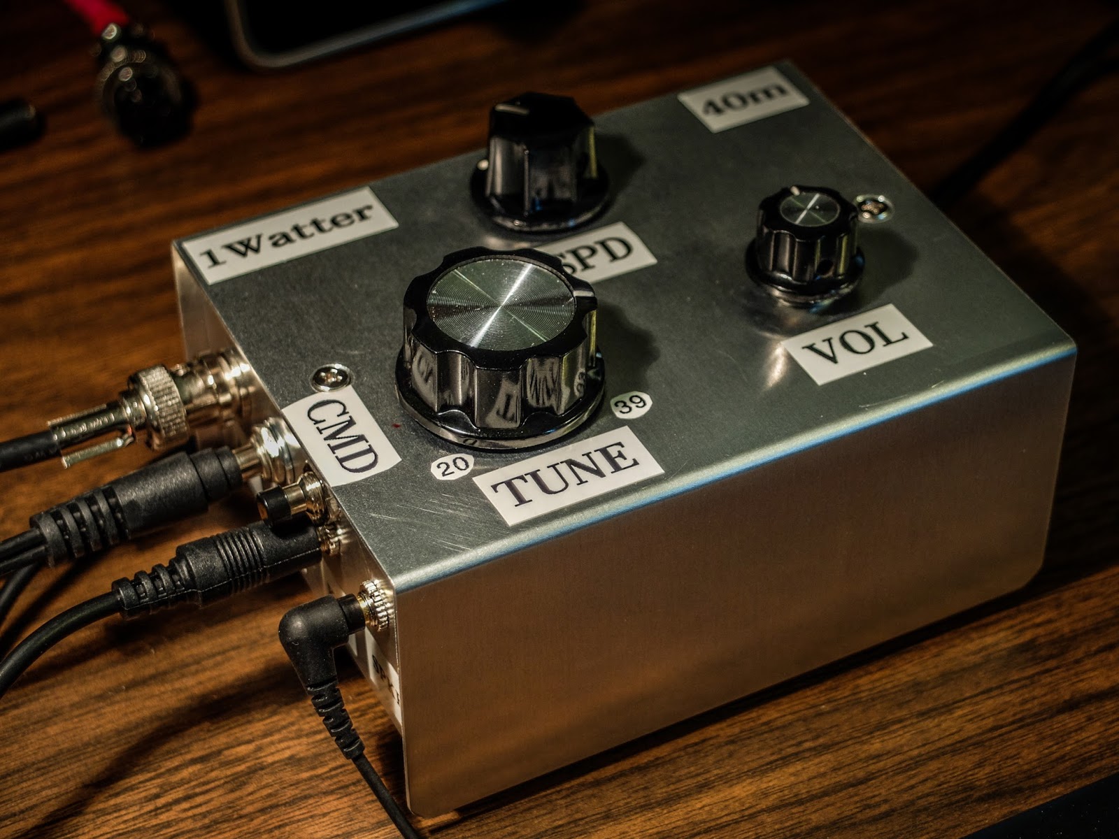
1Watter in enclosure with all the proper connectors for the case


Information on case and knobs:
JPM Supply


CodeItemQtyPriceGrand Total
44088Aluminum Electronics Project Box 4.73 x 3.62 x 2.09 inches Enclosure1$7.99$7.99
62411Round Knob 1/4 Shaft with White Indicator1$0.99$0.99
62424Knob, 1.28" Black with white indicator, 6mm Shaft with set screw1$0.89$0.89
62405Round Star Knob 1/4 Shaft with White Indicator1$0.99$0.99

Saturday, December 5, 2015

Junkbox eardrum saver

Volume control for my volume control

So my lovely 1977 Ten-Tec Century/21 transceiver has not-so-lovely CW sidetone.  The sidetone has a pronounced thump or pop on the first key-down of each letter. When listening through the external speaker it's not too noticeable but when wearing headphones it becomes really obnoxious and even painful during a long ragchew.

There is a variable resistor on the C21's audio board for the side-tone but it doesn't eliminate the pop, in fact it makes it more pronounced as the sidetone volume is reduced and it is least pronounced when the volume is increased but then the sidetone is really, really loud, especially when using headphones.

Besides that, the headphone AF output is quite hot anyway even at the lowest AF level with my comfy Sennheiser headphones so I figured I could benefit from an in-line volume control.  

I looked at ordering one but I've used in-line volume controls built-into headphones before and they always seem to go bad within a year so I scrounged around in my junkbox and found some variable resistors and volume pots.  I tested them and found one that goes from 10 ohm - 475 ohm so it seemed to fit the bill.  I fished around some more and found a 1970s era Switchcraft 1/4" phono plug and some more old lamp cord and I was in business.

I used the end cap from an old USB thumb drive to lend some mechanical strength to the attachment of the variable resistor to the cord.  Wallah, in-line volume control with a hip see-through enclosure.

Junkbox, in-line headphone volume control
It works great.  Now I can tone down the killer sidetone audio at the headphone jack from my old beauty and as a bonus, the old Switchcraft plug is a historical match for the C21. The variable resistor let's me tailor it to my ear fatigue.  I know this is a simple little 5 minute project but sometimes those are the ones that you appreciate the most.

Free in-line volume control
might buy me a couple of months of hearing in the future
That's all for now.

So lower your volume and raise your hearing longevity

73/72
Richard - N4PBQ

Friday, May 27, 2016

Let your fingers do the talking...

Let them play different instruments

Keys left to right
Nye Viking, Kent Hand key, Vibroplex Original Bug, N3ZN ZN-QRP paddle, Palm Single paddle
My collection of keys has grown over the past few months and I find that I like each for their particular qualities.

Keys from left to right

The Nye Viking is somewhere between a traditional J-38 low style American key and a tall European style.  At first I couldn't get any sort of coordination with it even after a couple hours of practice and it stayed in the closet for a few months.  Eventually I wanted to leave a key hooked up to the old Century/21 so I didn't have to move the output of my external keyer so the Viking came back out.  I've finally become accustomed to it and am even beginning to enjoy it as much as the Kent.  I'm amazed at how different two straight keys can be.

The Kent Hand key continues to be my favorite key for straight key operation.  The Kent is operated using your entire arm off the desk and when I send using it above 15wpm I get the entire desk shaking with the motion.  My desk light starts casting dancing shadows across the equipment from the vibration and with the clacking of the key and the blare of the sidetone the world of CW becomes visceral.

The Vibroplex Bug remains at the center of the collection because I have some strange affinity for the quirky bug.  I use it on every QSO where I hear another bug operator or with SKCC operators that are sending faster than 17wpm.  It has a non-cosmetic, yet effective, weight added from an old steel spacer to slow it down to a range of 21wpm to 16wpm and some dental floss around the DIT contact spring to reduce the potential bounce which results in scratchy sounding DITS.

The N3ZN ZN-QRP paddle is a work of art and when I'm working higher speed CW it's my go-to key.  The carbon fiber finger pieces and lightweight clickety action always puts a smile on my face.  I keep it connected to the external Ham Keyer which has a handy knob to for quickly adjusting keyer speed.

The Palm Single to the right is magnetically mounted to a steel base a friend made for me. I pull it off the base when I go portable as it's my go-to key for all my portable operations.  But when I'm at the home station I leave it hooked up to the keyer input on the Ten-Tec Eagle because the Eagle's keyer is only Iambic-B mode and I just can't get used to "B-Mode".  Using a single, non-iambic paddle eliminates the weird timing of the B iambic mode.  I really should learn mode-B since it seems to be standard on Ten-Tec and Kenwood radios. 


The 3 stars in the center are the Kent Hand key, Vibroplex Original Bug and the N3ZN paddle

The 3 keys in the middle (Kent Hand key, Vibroplex Bug and N3ZN paddle) remain hooked up to the Ham Keyer and I move the output of that keyer to whichever rig I'm primarily using at the time.  That keyer uses Iambic-Mode-A which I'm comfortable with and it debounces the scratchiness of the Bug.  I hook the output of the keyer up to either the PTT line on the Eagle or the secondary key input on the KX3.  When using the C21 I just use the Nye straight key.

Debouncing a Vibroplex Bug


Side story on the Bug... If you get a Vibroplex bug and hook it up to the PTT line of your radio you may find that you're missing DITS or that the output sounds broken or scratchy.  The PTT line of many radios is not "buffered" meaning it is reacting to every contact closure.  On a bug, the DIT contact is actually bouncing potentially hundreds of times a second since the contact force is so light and doesn't make a clean closure.  Many keyers will filter out those multiple contacts or bounces.  My old HAM KEYER weight control actually serves as a DIT weight control for the manual keys as well so it's ideal for use with the bug.

KE6EE offered me this nice explanation of what was going on:
The more usual term for the process of dealing with problems of contact closure is "debouncing." Google and you will find lots of interesting visuals and explanations.

The actual start and finish of contact closures and openings in switches, relays and keys, is not a simple off-and-on process but a series of "bounces." Dit contact closures on a bug are likely to be very bouncy. 

Bug dit contact design and bug maintenance and adjustment are critical for minimizing bounce. Ops with Vibroplex-style dit contacts often put a piece of rubber or plastic foam in the U-shaped dit contact spring. The Begali bug uses a unique pointed and spring-loaded dit contact. Many bug ops, from my observations on the air, do not adjust their dit weight properly to minimize a scratchy sound.

Transmitter keying circuits are usually "debounced" in various ways, the simplest perhaps being to put a capacitor across the key contact circuit. A PTT circuit doesn't need to be debounced so it isn't. Keyers often have debounce circuits designed to be used with straight keys and bugs.

Try different keys

So if you are getting into CW try some different keys.  I think you'll be surprised by the differences and find that your mood or situation will dictate the use of one key over another.   Morse keys on the used market aren't expensive if you shop carefully so you can build quite a collection.  They also tend to hold their value if you find that you've obtained a key or two that you just can't grok.


My ever changing station sporting a spiffy new chair

 That's all for now

So lower your power and raise your expectations

73
Richard, AA4OO

Friday, December 30, 2016

Peace on Earth... and in the Shack

Quieting a noisy power supply

With a bit of time over the Christmas break I'm finally getting around to work on things that have bugged me for a while... like my noisy power supply.


My TenTec Century 21 doesn't have a fan and it has a built-in power supply, so no fan noise.  My Elecraft KX3 has no fan, so no fan noise and it can run all day from a small 12v battery.  My TenTec Eagle only runs fans when the finals get hot and even then the fans are in the interior of the case and are speed controlled, low-speed, high-volume dudes that I have never heard. I can feel air moving through the Eagles vents so I know the fans work, their just silent.  But the Eagle needs an external power supply.

The calming sound of CW wafting forth from the Eagle is soon destroyed by a sound not unlike an air-raid siren emitted from my Astron power supply as it kicks its fan into high gear

Problem


My power supply has a single, large fan that makes me jump every time it whirs into action.  Admittedly, my power supply was near the bottom of the range in the Astron lineup.  I assume they have speed controlled fans, or at least quieter fans further up the product line.  I purchased this one used, about 9 years ago, so who knows, maybe their new power supply's have speed controlled fans.

Anyway, on my model, the muffin fan produces a hurricane force blow switched by a thermocouple located on the transistor heat sink (right hand side).  It is a very simple design... when the thermocouple trips it closes a circuit to the fan.  When heat sink temperature falls below the threshold it cuts off.  So the fan is either ON or OFF.  Normally the fan doesn't come on when the rig is idling, and it will only come on once in a while at QRP levels.  I just never know when, but I'm always anticipating... like the jerk kid that would flick your ear when he walked by back in school (hmm, I feel as though I may have some un-dealt with issues from childhood).

The fan seems to have a knack for coming on when I'm working a station that is fading into the noise and remaining on until I've missed some key piece of the QSO.

Solution


What I wanted to do was keep the air moving like a gentle breeze rather than a pulsing Category 5, but still allow the fan to come on full speed if needed.  So the trick was to get the fan to run continuously at a slow speed whenever the power supply was on but still allow the thermocouple to give it the gas.

The label on the fan says it's 1.4w 12v... I rummaged through my junk box looking for 2w and higher resistors.   I didn't find a lot to choose from, since I just haven't been at this electronics building stuff all that long.  I had a number of very low resistance ones from 2 ohm to 20 ohm and everything else was 650 ohm or higher.

I clipped test leads to both sides of the thermocouple on the heat sink that controls the fan.  I wanted to try different resistor values to see what happened.  Predictably, the low value resistors acted pretty much like a closed circuit and the fan ran near full speed.  I could have strung a number of the low value resistors in series but that seemed messy and the values were mostly very low.  I tried my next lowest value 2-watt resistor, 650 ohm.  The fan didn't even come on with 650 ohm resistance.  I didn't have anything in between so I put two of the 650's in parallel and it turned verrrry slooowwwly.

You can find TOTAL RESISTANCE in a Parallel circuit with the following formula: 1/Rt = 1/R1 + 1/R2 + 1/R3 + ... "

Ok I was on to something.   Turned out that 5 of the 650 ohm 2w resistors in parallel did the trick... That turned out to be near 130 ohm.  I left them hooked up for an hour or so to make sure more current wasn't being pulled than I expected, and they only became slightly warm to the touch so I figured my redneck engineering was good to go.  I soldered the bundle of resistors leads in parallel and used some heat shrink to keep it neat.

I've used the power supply for a good part of a day and it stays nice and quiet now.  Not silent, but good enough to where I can't hear it at all with my headphones on.  A key down test into a dummy load at QRO power repeated times confirmed that the fan will go to full speed after a while but in normal operation, the thermocouple never triggers.

By my low standards, I deem this a success.


redneck ham engineering

Perform this mod at your own risk

This is certainly not a manufacturer approved modification and your power supply may be quite different than mine so tinker at your own risk.  Oh, and be careful when you have the cover off a power supply there are multiple, high voltage components in there.  Make sure it's unplugged and has plenty of time to bleed off power from the big capacitors before you start messing with anything in there.


That's all for now

So lower your fan speed and raise your quality of life...

72/73
Richard AA4OO

Tuesday, November 14, 2017

Thank you for my signal report

3 numbers can mean a lot


QRP operators strive to make the most out of a little.  So when we receive a signal report it means a lot to us.  But the common signal report, given using the R-S-T System, seems often to be misunderstood by some amateur radio operators.

RST has 3 elements:
  • R stands for Readability.  How easy or difficult is it to copy the characters or words being sent on a scale from 1 to 5, with 1 meaning unreadable ranging up to 5 meaning perfectly copy-able.
  • S stands for Signal Strength.  How strong is the signal on a scale from 1 to 9, with 1 being barely perceptible up to 9, being extremely strong.
  • T stands for Tone.  This is only used to describe a CW signal's tone.  Given modern transceivers there are few cases where you'd send anything other than a 9 meaning perfect tone, devoid of ripple or modulation. You'll rarely hear a report with a Tone report other than 9, but if you hear ripple or modulation artifacts you may send lower numbers but it will likely just confuse the other operator.  If you hear chirp (a rising or falling tone) you may wish to append a 'C' to the RST to indicate that.
I want to concentrate on Readability and Signal strength.

Readability

I believe most of us are guilty of focusing on the signal strength portion of the report rather than readability.  But readability can convey a lot to the operator receiving the report.  

For instance if you have a lot of local noise or if the band is noisy due to magnetic disturbance or there's QRM or QRN readability may be difficult.  Similarly, if the operator is using poor technique and running letters or words together that affects readability.

It's possible that signal strength may be good or even moderately strong (6 or 7) but for some reason copy is difficult.  It would be worthwhile to send a 2 (Barely readable, occasional words distinguishable) or a 3 (Readable with considerable difficulty) for the 'R' portion of the signal report as in 359.  Then follow up with WITH QRM or WITH POOR SPACING, to make the other operator aware that you're having trouble copying.

I will occasionally have an operator send me a 3 for R but it seems to always be related to low signal strength.  If someone sends you a 3 or a 4 and it's not followed by an equally low signal strength number inquire as to the difficulty in readability.  It may be something you can correct on your end.

Signal

Signal seems obvious but it's not.  

I believe that many operators use the reading on their S-meter to report the Signal strength but different manufacturers calibrate their S-meters quite differently. The difference between S-units is supposed to be 6 dB but that's often not the case.  On many rigs the use of the preamp or the attenuator also effects the displayed S-meter reading.  So the S-meter is not an accurate reflection of what Signal strength is supposed to convey.  

My old Ten-Tec Century/21 doesn't even have an S-meter.  Neither do my homebuilt QRP radios.

So, what should we be using?  Well how about the actual meaning of the system:
  1. Faint—signals barely perceptible
  2. Very weak signals
  3. Weak signals
  4. Fair signals
  5. Fairly good signals
  6. Good signals
  7. Moderately strong signals
  8. Strong signals
  9. Extremely strong signals
Obviously this is a subjective report, but on my KX3 my S-meter may read 2 when the signal actually sounds Good (6), so I send a 6 even though the meter reads 2.  If I were to send the other station the S-meter reading of 2 they'd assume I'm barely copying them, because I sent them a 529.

I think you can start to see the point.  Use the system as it was designed, before radios had S-meters and the Signal report will have more meaning to the station receiving the report.

My Ten-Tec C21 doesn't have an S-meter but it does have AF and RF gain controls.  I will commonly run my AF gain at a high level and use the RF gain to control the volume of the received signal.  This increases the SNR (signal to noise) and gives me a relative gauge of how strong the sender is.  If I have my RF gain turned all the way down and still clearly hear the other station they have an extremely strong signal (9).  If I have to turn my RF gain all the way up just to copy then the signal is very weak, or faint (2 or 1).  In between those extremes I offer a relative report based on the signal strength  I  am hearing.

So, use the system as it was intended

So, reconsider how you give a signal report.  Think about the original intent of the R-S-T System and you'll be conveying far more information in your report that may help the other station know for certain how they are being heard.

I start most QSOs at QRP levels.  If the other station sends me a report that is below a 5 in readability or a signal strength 5 or below I change antennas or raise power, if I'm able, to make their copy of my station more pleasurable, but if they send me a 599 when they are barely copying me or losing me in QSB then how can I know to make a change?

Maybe this is a radical idea but for my own operation I will strive to start sending more accurate reports and help the other station truly know how they are being copied.


That's all for now...

So lower your power and raise your expectations

72/73
Richard, AA4OO

Saturday, December 30, 2017

Don't forget -- Straight Key Night 2018 is tomorrow !

Straight Key Night -- 2018

Don't forget January 1st, 2018 starting 00:00 GMT (7pm EST Dec 31) is the start of Straight Key Night 2018.  Bring your tired, old equipment on-air and mash your favorite mechanical key.  This is not a contest, just an opportunity to make lots of fun QSOs.

I'll be on the air with my 1977 Century/21 using my Junker Straight key and Standard Vibroplex Bug.


ARRL has details on their website... http://www.arrl.org/straight-key-night

Video from 2018 SKN

If you hang in there until the 2:08 mark you'll see my new, spiffy, dual camera angle recording method that I plan to use in all my videos.


So, lower your power, and raise your expectations...

72/73
Richard AA4OO

Thursday, March 8, 2018

Oscilloscope now on the bench

Tektronix 475 Oscilloscope and Android Signal Generator App

When I was debugging problems with my Ten-Tec Century/21, and especially my problematic one-watter kit, I needed to see more than DC voltages.  I carried my problem stuff to my friend Paul to see what his scope and signal generator revealed. 

Why would a ham need a scope?  Audio and RF are both AC (alternating current) and a voltmeter alone doesn't offer much insight into that world of voltage across time and phase.

I almost bought an inexpensive digital scope last year, then thought better of it.  Then I almost bought a featured digital scope and checked my wallet and thought better of it. A good digital scope in the 100 Mhz and up range from reliable sources costs upwards of $500.  On the other hand, older professional scopes that have been well maintained and kept in calibration are excellent choices and will last a lifetime.  You do give up handy on screen cursors for measurements, so you have to count divisions by hand and do the math.  You also don't have digital storage in a digital scope, but smart phone cameras and video can make up for that.  

When I saw this recently calibrated Tektronix 475 listed in the classifieds on eHam.net for a nice price, I decided it was time to step into the world of visualized AC.

Watching a capacitor charge 250 times a second
The lines are a bit wide because the signal source was noisy

Tek 475 Specs

The Tektronix 475 is a portable (30 lbs), dual-trace oscilloscope with dual time-bases similar to the 465, but with 200 MHz bandwidth and a maximum vertical sensitivity of 2 mV/Div. It is all solid-state except for the CRT. It was introduced in November 1972.  

This scope cost $3,000 when it was new.  Now you can find them in good condition for less than $200.

  • Bandwidth --  200 MHz (475), AC cutoff 10 Hz, switchable BW limit 20 MHz
  • Rise time -- 1.75 ns (475)
  • Deflection -- 2 mV/Div to 5 V/Div, 1-2-5
  • Cascaded mode -- 400 μV/Div, 50 MHz with CH1 input connected to CH2 VERT SIG OUT
  • Time base -- 10 ns/Div to 500 ms/Div, 1-2-5, and ×10 magnifier
  • Input impedance -- 1 MΩ // 20 pF
  • Triggering -- 0.3 Div (int) or 50 mV (ext) to 40 MHz, increasing to 1.5 Div/250 mV at 200 MHz; AC coupling >60 Hz; LF REJ >50 kHz, HF REJ <50 khz="" li="">
  • X bandwidth -- 3 MHz
  • Z axis input -- 5 Vp-p, 50 MHz
  • Calibrator -- 1 kHz, 30 mA / 300 mV square wave
  • Outputs -- CH2 Vert Signal Out, 20 mV/Div into 1 MΩ or 10 mV/Div into 50 Ω; A and B +GATE OUT, +5 V; Probe power jack
  • CRT -- 8 × 10 cm², P31 phosphor (P11 opt.)
  • Power -- 110, 115, 120, 220, 230 or 240 VAC ±10%, 48-440 Hz, max. 100 W

Real knobs and switches

One advantage of an analog scope is that there is a labeled switch or knob for every function. No need to dig through menus to figure out how to do something.  To me this is the a true advantage to finding a well calibrated, analog scope.


An oscilloscope needs a function generator

An scope let's you visualize AC within a circuit, but when you testing  something you often need to inject AC into that circuit.  That's the role played by a function generator.  Function generators allow you to choose a frequency and a wave type (sine, triangle, square, etc.), or sweep across frequencies.

In general, the higher the frequency they support the more they cost.

If you have a mobile device you can get one that uses your headphone jack as output up to 22 kHz for free...


For a free app it is very nice.  It outputs sine waves very well, triangle waves are a bit soft pointed and square waves are for entertainment purposes only.  But it is free so I won't complain.  In the image below you can see the oscillations as it tries to generate a square wave but the audio amplifier of the mobile device just doesn't have that kind of control.

Frequency Generator App set to 1 kHz

Square Wave?

Square waves are not

Reduce the time base to zoom in

Yea, square wave.... not so much

The square wave is bad but sine and triangle waves look good until the frequency get's near the top of the range or the amplitude is raised too high.

Sine Waves look good

Triangle waves are on as well until you go up in frequency


The free app is inadequate for bench testing

While I appreciate that this would be a useful, portable signal generator for testing audio circuits, I'll be ordering a purpose-built function generator because generating clean square waves is an important test signal to be clean.  I also will need a generator that works above audio frequencies, hopefully up the the IF frequencies of the some of the equipment I'm testing.

Only the beginning

Having an oscilloscope is a new adventure for me.  I have another 1-watter kit ready to build that I've been holding off on because I wanted a scope for troubleshooting.  In the meantime I'm using the scope to watch transistors trigger and measure the timing circuits I'm building and learning how to control the scope.  The Tektronix 475 is a feature-rich analog scope.  If you plan to fix your own equipment or do some homebrew electronics work a scope can come in handy.


That's all for now

Sow lower your power and sample it with a scope

72/73
Richard AA4OO

Tuesday, December 27, 2016

Go straight on Jan 1, 2017 with the Navy

ARRL Straight Key Night is January 1 starting 0000 UTC


I have a new straight key for the upcoming ARRL Straight Key Night...

Navy Flameproof Key in need of some TLC

A recent low-bid, on a famous auction site, netted me this Navy Flameproof key.  A mismatched screw and nut from my Nye Viking key is serving  as the closure spacing adjustment until I get a replacement screw and nut specific to the Flameproof from JH Bunnell Co.  I've been using it on the air and it has a distinctly different feel from my other straight keys.  There's a lot going on inside that little enclosure.

I will have this key as well as my Kent Hand Key on-the-air during this year's straight key night driving my 1977 TenTec Century 21 CW rig

Kent Hand Key in front of TenTec C21


ARRL Straight Key Night


Straight Key Night (aka SKN) occurs on the first day of each year (beginning at 0000 UTC) and runs for 24 hours.  In addition to dusting off your straight key, it has sort of become a tradition to drag out all the vintage equipment you can muster and get it on-the-air.  


What should you expect on SKN?

Last year I heard old tube rigs with a power supply issues causing chirp to rival the loveliest song bird and shaky FISTS that required full concentration to decipher.  I had a grand time hearing paddle-only operators trying to regain the knack for using their straight keys, and I could almost smell the dust burning off the tubes of those old rigs that hadn't been fired up in a year.

When you send your CQ also send SKN if you'd like.  This is not a contest and there are no awards for the most contacts, so have some good ragchews and get to know the fellow on the other side of the key.  Enjoy the slow(er) pace of working straight key stations and settle in for interesting QSOs.

Although you'll hear a lot of vintage equipment, that is certainly not required to get on the air. If you don't have a straight key you might just have a clothespin and some screws...


SKN times...


Don't forget SKN begins at 0000 UTC which means for those of you on the East coast of the US SKN starts 7pm December 31st and for those of you on the left coast it begins at 4pm, So you can get a few hours in before the bell tolls 2017 for your time zone.  


SKN runs for 24 hours, but don't put away your straight key just because it's over.  Join in the fun with the SKCC all year 'round.


That's all for now

So lower your power and raise your expectations...

72/73
Richard, AA4OO  

Saturday, March 26, 2016

The Eagle has landed

Ten-Tec Eagle -- A CW masterpiece

I've had the opportunity to bring another wonderful radio from Ten-Tec into the shack.  The Ten-Tec Eagle.

Ten-Tec Eagle HF transceiver
The Eagle is NOT a feature laden radio and using it is a bit quirky.  

There are no menus on the Eagle.  The dual-function buttons you see are what you get. The multi-knob allows adjustments for the various functions.

What it does have that is so common with the Ten-Tec line of radios is absolutely wonderful sounding audio and beautiful full QSK with no strange audio artifacts at full-break-in.  It is a pleasure to work weak stations.  This particular radio has three 4-pole filters for the IF at 2.4kHz, 600Hz and 300Hz.  They are automatically selected as the dedicated bandwidth knob is adjusted, resulting in smooth and clear filtering of CW stations.

I also have a Elecraft KX3 and while it has similar receiver specifications, listening to weak CW with it has a lot of digital artifacts that are not present on the Eagle.  I can work a weak station with the Eagle and not be fatigued at the end of the qso.

It also has a nice ATU capable of matching up to 10:1 SWR antennas and of course supports SSB.  It covers 160m-6m and can do FM if the 15kHz filter is installed.

Eagle beside its much older brother, the Ten-Tec Century/21

CW the way it was meant to be heard


The solar conditions have been extremely poor over the past week that I've used the rig and are likely to be this way for a few years to come.  It's nice to have a rig that makes these poor conditions still enjoyable.

If you love CW do yourself a favor and try a Ten-Tec.  They are pricey compared to other rigs and they do not come close competing on price-per-feature but Ten-Tec receivers make for amateur-radio bliss.

That's all for now

So lower your power and raise your expectations

72/73

Richard, AA4OO

Saturday, December 19, 2015

Vertical Space

Taking my station to new heights

My burgeoning QRP station was getting messy, having stuff strewn all over the desk, so I made a shelf from some junk laying around to give me some vertical space. It is much more organized now.
A shelf helps
Left to right top shelf:
Ozark Patrol Regen Receiver Kit, MFJ Versa Tuner providing both tuning and antenna switching duties, Two Position Rig switch on top (blue box), Ham Keyer (circa '78) electronic keyer

Left to right under shelf:
Yaesu HT connected to home-brew J-Pole in attic, two switching power supplies, VHF/UHF meter, Elecraft KX3, Ten-Tec Century/21 (circa '77), Homebrew frequency counter on top of TT)

Three keys:
Bencher paddles, Vibroplex Bug, Kent Hand Key
That's all for now.

So lower your power and raise your expectations

73/72
Richard N4PBQ

Sunday, January 17, 2016

Get a taste of the RF coming and going

Elecraft CP1 - A tasty RF treat

I had some time this afternoon to assemble another Elecraft mini-module kit.  This time it was the Elecraft CP1 directional coupler.

Elecraft CP1 Kit

Couple what?

Ah, so if your new to this like me you might be asking what does a coupler do?  Well it sorta listens in on the signal going out (forward) and reflected (back) and is able to send an attenuated sample of the signal to other devices.  It attenuates the sample by either 20db or 30db depending on how you build the kit.

The 20db version is good for signals 25 watts and less so that's the way I built it.  It was easy to build but my glue under the second toroid wasn't strong enough and you can see it popped up a bit.  Also the Elecraft instructions had one confusing instruction concerning mounting the toroids.  The instructions say "... When wound and mounted correctly, the enamel wire will emerge from the top of each core and connect to the top hole at each inductor location".  Well when you wind a toroid only one of the wires can "emerge from the top of the core" while the other comes from underneath.  This confused me for a minute until I finally just went on with the install.  Anyway, if you're a stickler for following instructions that one may cause a moment of pause...

The switches for the two outputs forward, reflected (J3, J4) are in the up position when they are not in use.  When the switch(es) are in the up position the 50 ohm 3 watt resistor(s) take the place of the switched off output.  Don't disconnect an output and leave the switch in the bottom position.  I'm not sure what will happen... maybe nothing, probably a bit of a mismatch on the SWR, or maybe it could be like "Crossing the streams" in Ghostbusters.  Your mileage may vary.

My uses for a coupler

My old Ten-Tec Century 21 has an analog VFO dial that gives me a good guess at where I'm at but I use an external frequency counter to give me more information.  I had it sorta rigged my frequency counter to sample the signal from RF leaked on the shield but I didn't really know how much power I was sending to the counter so this coupler allows it, as well as other devices, to be safely connected to the transmitted signal.

I also plan to use the coupler for IMD tests using a oscilloscope and other projects.  It's  handy device to have in your collection.

My confusion

I will admit I am still such an idiot when it comes to understanding how this stuff works.  After I built it I was testing continuity and saw that input/output (J1, J2) both showed a short from ground to center pin on both BNC connectors.  I thought I'd mis-soldered something and spent the next two hours unsoldering components and trying to trace the fault...

There was no fault.  The way this thing works is a bit of mystery to me but as best I can tell it simply reverses the phase of the signal coming in one side (J1) and leaving the other (J2) and as far as continuity tests go, EVERYTHING has almost zero impedance.  I'm still bewildered but it's AC not DC so my continuity tests don't mean much.

But in the end - It works

I finally just resoldered it, scratched my head and thought I'd give it a try.  I connected the coupler between my radio and a dummy load and transmitted a watt and noted that the SWR on the radio was fine.  Then I hooked up my frequency counter and it worked like a charm sending an attenuated signal to J3 for the frequency counter.

My MFJ watt meter doesn't seem to be all that accurate but I did a power test with it both in-line and absent.  My MFJ watt meter measures 300w / 30w so it isn't very accurate at QRP levels.  But I noted a slight difference in power reported when the coupler was in-line.  If I had to guess by "Mark-One-Eyeball" I'd say the coupler was stealing about 1/2 watt.  Maybe a bit more so that's something to consider.  I'll know better once I build my Elecraft watt meter since it's accurate down to a tenth of a watt.

That's all for now

So lower your power and raise your expectations

72/73
Richard, N4PBQ